ENERGY_EFFICIENCY_IN_ELECTRICAL_UTILITIES
(Chapter 8:Lightening System)
Introduction
Most natural light comes from the sun, including moon light. Its origin makes it completely clean and
it consumes no natural resources. But man-made sources generally require consumption of resources,
such as fossil fuels, to convert stored energy into light energy.
Light is usually described as the type of electromagnetic radiation that has a wavelength visible to the
human eye, roughly 400 to 700 nanometers. Light exists as tiny “packets” called photons and exhibits
the properties of both particles and waves. Visible light, as can be seen on the electromagnetic spectrum,
as given in Figure 8.1, represents a narrow band between ultraviolet light (UV) and infrared energy
(heat). These light waves are capable of exciting the eye’s retina, which results in a visual sensation
called sight. Therefore, seeing requires a functioning eye and visible light.
The lumen (lm) is the photometric equivalent of the Watt, weighted to match the eye response of the
“standard observer”. Yellowish-green light receives the greatest weight because it stimulates the eye
more than blue or red light of equal radiometric power:
1 Watt = 683 lumens at 555 nm wavelength
The best eye sensitivity, as seen from Figure 8.2 is at 555 nm wavelength having greenish yellow
colour with a luminous efficacy of 683 lm/Watt.
Three primary considerations to ensure energy efficiency in lighting systems are:
1. Selection of the most efficient light source possible in order to minimize electricity
consumption and cost.
ii. Matching the proper lamp type to the intended work task or aesthetic application, consistent
with color, brightness control and other requirements.
iii. Establishing adequate light levels without compromising productivity improve security and
increase safety.
Basic Parameters and Terms in Lighting System
Luminous flux: The luminous flux describes the quantity of light emitted by a
light source. It is a measure of a lamp’s economic efficiency.
The most common measurement or unit of luminous flux is the lumen (Im).
The lumen rating of a lamp is a measure of the total light output of the lamp. Light
sources are labeled with an output rating in lumens.
Illuminance (E): is the quotient of the luminous flux incident on an element of
the surface at a point of surface containing the point, by the area of that element.
The lighting level produced by a lighting installation is usually qualified by the
illuminance produced on a specified plane. In most cases, this plane is the major
plane of the tasks carried out in the interior and is commonly called the working
plane. The illuminance provided by an installation affects both the performance of the tasks and the
appearance of the space. Lux (Ix) is the metric unit of measure for illuminance of a surface. One lux
is equal to one lumen per square meter. I!luminance decreases by the square of the distance (inverse
square law).
The inverse square law defines the relationship between the illuminance from a point source and
distance. It states that the intensity of light per unit area is inversely proportional to the square of the
distance from the source (essentially the radius).
Where, E = Illuminance in lux (Im/m2), I = Luminous flux in lumen (Im) and d = distance in m
An alternate form of this equation which is sometimes more convenient is:
Distance is measured from the test point to the first luminating surface - the filament of a clear bulb
or the glass envelope of a frosted bulb.
Example:
The illuminance is 10 lm/m2 from a lamp at 1 meter distance. What will be the illuminance at half the
distance?
Average maintained illuminance: is the average of illuminance (lux) levels measured at various
points in a defined area.
Circuit Watts: is the total power drawn by lamps and ballasts in a lighting circuit under assessment.
Luminous Efficacy (Im/W);: is the ratio of luminous flux emitted by a lamp to the power consumed
by the lamp. It is a reflection of efficiency of energy conversion from electricity to light form. Unit:
lumens per lamp Watt (Im/W).
Lamp Circuit Efficacy: is the amount of light (lumens) emitted by a lamp for each Watt of power
consumed by the lamp circuit, i.e. including control gear losses. This is a more meaningful measure
for those lamps that require control gear. Unit: lumens per circuit Watt (Im/W).
Installed Load Efficacy: is the average maintained illuminance provided on a horizontal working
plane per circuit watt with general lighting of an interior. Unit: lux per Watt per square metre
(lux/W/m/2).
Installed Power Density: The installed power density per 100 lux is the power needed per square
metre of floor area to achieve 100 lux of average maintained illuminance on a horizontal working
plane with general lighting of an interior. Unit: Watts per square metre per 100 lux (W/m7/100 lux)
Color rendering index (CRI): is a measure of the effect of light on the perceived color of objects.
To determine the CRI of a lamp, the color appearances of a set of standard color chips are measured
with special equipment under a reference light source with the same correlated color temperature as
the lamp being evaluated. If the lamp renders the color of the chips identical to the reference light
source, its CRI is 100. If the color rendering differs from the reference light source, the CRI is less
than 100. A low CRI indicates that some colors may appear unnatural when illuminated by the lamp.
Luminaire: is a device that distributes filters or transforms the light emitted from one or more lamps.
The luminaire includes all the parts necessary for fixing and protecting the lamps, except the lamps
themselves. In some cases, luminaires also include the necessary circuit auxiliaries, together with the
means for connecting them to the electric supply. The basic physical principles used in optical luminaire
are reflection, absorption, transmission and refraction.
Control gear: The gears used in the lighting equipment are as follows:
¢ Ballast is a current limiting device, to counter negative resistance characteristics of any
discharge lamps. In case of fluorescent lamps, it aids the initial voltage build-up, required
for starting. In an electric circuit the ballast acts as a stabilizer. Fluorescent lamp is basically
an electric discharge lamp with two electrodes separated inside a tube with no apparent
connection between them. When sufficient voltage is impressed on these electrodes, electrons
are driven from one electrode and attracted to the other. The current flow takes place through
an atmosphere of low-pressure mercury vapour.
¢ Since the fluorescent lamps cannot produce light by direct connection to the power source,
they need an ancillary circuit and device to get started and remain illuminated. The auxiliary
circuit housed in a casing is known as ballast.
¢ Ignitors are used for starting high intensity discharge lamps such as metal halide and sodium
vapour lamps. Ignitors generate a high voltage pulse or a series of pulses to initiate the
discharge.
Light Source and Lamp Types
Lamp is equipment, which produces light. Light is that part of the electromagnetic spectrum that is
perceived by our eyes. A number of light sources are available, each with its own unique combination
of operating characteristics viz., efficacy, colour, lamp life, and the percent of output that a lamp loses
over its life.
Based on the construction and operating characteristics, the lamps can be categorized into three groups:
incandescent, fluorescent and high intensity discharge (HID) lamps. HID lamps can be further classified
as sodium vapour, mercury vapour and metal halide lamps. The most commonly used lamps are
described briefly as follows:
1) Incandescent lamp
The principal parts of an incandescent lamp also known as GLS lamp (General Lighting Service lamp)
include the filament, the bulb, the fill gas or vacuum and the cap. Incandescent lamps (Figure 8.3 A&B)
produce light by means of a wire or filament heated to incandescence by the flow of electric current through it. The filament is enclosed in an evacuated glass bulb filled with inert gas such as argon,
krypton, or nitrogen that helps to increase the brilliance of lamp and to prevent the filament from
burning out.
Reflector lamps: Reflector lamps are basically incandescent, provided with a high quality internal
mirror, which follows exactly the parabolic shape of the lamp. The reflector is resistant to corrosion,
thus making the lamp maintenance free and output efficient.
2) Halogen lamp
It has a tungsten filament and the bulb filled with halogen
gas (Figure 8.4). Current flows through the filament and
heats it up, as in incandescent lamps. These lamps
therefore generate a relatively large amount of heat. The
use of halogen increases the efficiency and extends the
service life compared with traditional incandescent
lamps. Low-voltage types are very small and are ideal
for precise direction of light, but they require a
transformer.
Tungsten atoms evaporate from the hot filament and
move toward the cooler wall of the bulb. Tungsten,
oxygen and halogen atoms combine at the bulb-wall to
form tungsten oxyhalide molecules. The bulb-wall
temperature keeps the tungsten oxyhalide molecules in
a vapor. The molecules move toward the hot filament
where the higher temperature breaks them apart.
Tungsten atoms are re-deposited on the cooler regions of the filament - not in the exact places from
which they evaporated. Breaks usually occur near the connections between the tungsten filament and
its molybdenum lead-in wires where the temperature drops sharply.
3) Fluorescent tube lamp (FTL)
It works by the fluorescence principle. A fluorescent lamp (Figure 8.5 A&B) is a glass tube containing
a small trace of a gas such as mercury vapor (for a white color), carbon dioxide (for green), neon (for
red color), etc., with a special fluorescent / phosphorescent coating on the interior surface of the tube.
It contains two filaments, one at each end of the tube and when the electrical supply is switched ON,
the contacts of the starter open and the filaments glow to heat up the gas contained inside the tube.
This action provides a voltage across its electrodes that set off an electric (gaseous mercury) arc
discharge in the tube. This generates invisible UV radiation that is high enough to ionise the warmed�up gas inside the tube. This ionised gas also called as “plasma”, excites the fluorescent coating so that
it gives out visible light. Ballast is needed to start and operate fluorescent lamps, because of the
characteristics of a gaseous arc. The luminous flux is highly dependent on the ambient temperature.
Fluorescent Lamps are about 3 to 5 times as efficient as standard incandescent lamps and can last about
10 to 20 times longer.
The different types of fluorescent lamps and their reference are given below:
Linear tubes
¢ T12-38 mm (1.5’diameter)
¢ T8-25 mm (1”diameter)
¢ T5 - 16mm (5/8”diameter)
¢ T2-6mm (1/4’’ diameter)
U-bent tubes
¢ T12-38 mm (1.5”diameter)
¢ T8-25 mm (1” diameter)
Circular tubes
¢ T9-38 mm (1.5’diameter)
¢T5 - 16 mm (5/8”diameter)
These four lamps vary in diameter (ranging from 1.5 inches that is 12/8 of an inch for T12 to 0.625 or
5/8 of an inch in diameter for TS lamps). Efficacy is another area that distinguishes one from another.
T5 & T8 lamps offer a 5-percent increase in efficacy over 40-watt T12 lamps, and have become the
most popular choice for new installations.
4) Compact fluorescent lamp (CFL)
Compact Fluorescent lamps (Figure 8.6) are compact /
miniature versions of the linear or circular fluorescent
lamps and operate in a very similar way. The luminous flux
depends on temperature. CFL’s use less power and have a
longer rated life compared to an incandescent lamp.
They are designed to replace an incandescent lamp and can fit into most existing light fixtures formerly
used for incandescent. CFL’s are available in screw type/ pin type which fit into standard sockets, and
gives off light that is similar to common fluorescent lamps.
5) Sodium vapour lamp
Low pressure sodium vapour lamp
Although low pressure sodium vapour (LPSV)
lamps (Figure 8.7) are similar to fluorescent
systems (because they are low pressure systems),
they are commonly included in the HID family.
LPSV lamps are the most efficacious light sources, but they produce the poorest quality
light of all the lamp types. Being a monochromatic light source, all colours appear black, white, or
shades of gray under an LPSV source. LPSV lamps are available in wattages ranging from 18-180.
LPSV lamp use has been generally limited to outdoor applications such as security or street lighting
and indoor, low-wattage applications where color quality is not important (e.g. stairwells). However,
because the color rendition is so poor, many municipalities do not allow them for roadway lighting.
High pressure sodium vapour lamp
The high pressure sodium vapour (HPSV)
lamp (Figure 8.8 A&B) is widely used for outdoor and industrial applications as the light is yellowish. Its higher efficacy makes it a
better choice than metal halide for these applications, especially when good color
rendering is not a priority. HPSV lamps differ
from mercury and metal-halide lamps in that
they do not contain starting electrodes; the
ballast circuit includes a high-voltage
electronic starter. The arc tube is made of a ceramic material, which can withstand temperatures up to
1300 °C. It is filled with xenon to help start the arc, as well as a sodium-mercury gas mixture.
6) Mercury vapour lamp
In a mercury vapour lamp (Figure 8.9) electromagnetic radiation is created from discharge within
mercury vapour, but the regime is different than that found in the normal fluorescent lamp. During
operation, the pressure within the lamp is in the range of 200 — 400 kPa (compared with only 1 Pa).
It is not possible to achieve the mercury vapour discharge in a cold lamp. For this reason, the lamp
also includes argon, and the initial arc is struck as an argon arc. The energy from this discharge
vapourises the mercury to get the main discharge going.
The mercury vapour lamp produces a much greater proportion of visible light than fluorescent lamp
and gives off a bluish white light. Phosphor coating can be given to improve the colour rendering index.
7) Metal halide lamp:
Metal halide lamp (Figure 8.10 A&B) can
be considered as a variant of high pressure
mercury vapour lamp (HPMYV). In addition
to mercury vapour and argon, this lamp
contains metal halide. The halides can be
a mixture of rare earth halides, usually
iodides or a mixture of sodium and
scandium iodide. The mercury vapour
radiation is augmented by that of the metals.
A highly compact electric arc is produced
in a discharge tube. A starter is needed to
switch on the lamp. The use of ceramic discharge tubes further improves the lamp
properties. The halides act in a similar manner to the tungsten halogen cycle. As the temperature
increases there is disassociation of the halide compound releasing the metal into the arc. The halides
prevent the quartz wall getting attacked by the alkali metals. By adding other metals to the mercury different spectrum can be emitted. Some lamps use a third electrode for starting, but others, especially
the smaller display lamps, require a high voltage ignition pulse.
Metal halide lamps have a significantly better colour rendering index than mercury vapour and can be
tailored by the choice of halides.

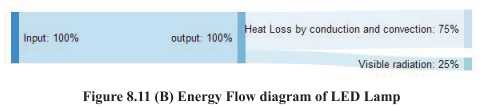
8) Light emitting diode (LED) lamp
LEDs produce light in a very unique way; they produce light via a process called electro-luminescence
(Figure 8.11), a process that starts by turning a semiconductor material into a conducting material. A
semiconductor with extra electrons is called N-type (negative) material, since it has extra negatively�charged electrons. In N-type material, free electrons can move from a negatively-charged area to a
positively charged area. A semiconductor with extra holes is called P-type (positive) material since it
has extra positively-charged gaps called holes. When excited with current the negative electron leaves
its atom and the P-type material’s positive attraction draws the free negative electron into its hole, and
the hole also moves toward the electron, so on and so forth.
As an electron travels to a hole, it carries energy, but in order to fit into the hole it must release any
extra energy, and when it does, the extra energy is released in the form of light. When we maintain a
steady flow of electrical current to the diode, it continues the process of allowing electrons to flow
from the negative charged material and fall into the positive charged holes which maintains a steady
stream of light out of the LED. The actual LED is quite small in size, usually less than one square
millimeter. Additional optical components are added to shape and direct the light. LED’s are made of
number of inorganic semiconductor materials, many of which produce different colour of light.
The efficiency of LED’s has now risen sharply and is currently up to 200 lumens per watt in the
laboratory and in some products available on the market (although more typical LED’s average output
varies from 50 to 130 lumens per watt).
Because of the low power requirement for LED’s, using solar panels becomes more practical and less
expensive than running an electrical wire or using a generator. Hence LED with battery backup for
remote application is very economical.
They do not radiate light in 360 degrees as an incandescent
does. The light will be bright wherever it is focused.
Unlike incandescent and fluorescent lamps, LEDs are not inherently white light sources. Instead, LEDs
emit nearly monochromatic light, making them highly efficient for colored light applications such as
traffic lights and exit signs.
However, to be used as a general light source, white light is needed. White
light can be achieved with LEDs in three ways:
Phosphor conversion, in which a phosphor is used on or near the LED to convert the colored light to
white light; RGB systems, in which light from multiple monochromatic LEDs (red, green, and blue)
is mixed, resulting in white light; and a hybrid method, which uses both phosphor-converted and
monochromatic LEDs.
Advantages of LED technology is as follows Low power consumption, Directional light output, High
efficiency level, Long life: upto ~100,000 hour life if junction temperature can be controlled, Instant
switching on with no warm up time, High resistance to switching cycles, High impact and vibration
resistance, No UV or IR radiation, Color control ability, allows dimming and Mercury free
LED’s also offer a number of promising environmental benefits, and they are often viewed as the future
of green lighting.
9) Induction lamp
Induction lamp is noted for ‘crisp white light output’. Uses a magnetic field to excite gases — has no
lamp parts to wear out. It consists of two main components: ballast and a sealed gas-filled bulb. Light
is produced via electromagnetic induction, without an electrode or any electrical connection inside the
bulb. Instead, high frequency electromagnetic fields are induced from outside the sealed chamber.
To produce light, the ballast supplies the electric coils with high frequency electrical current. The
ferrite magnets on either side of the bulb then emit electromagnetic fields which excite electrons within
the bulb.
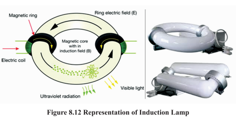
As the electrons accelerate inside the bulb, they collide with mercury atoms and produce ultraviolet
(UV) light radiation. The UV light then causes the special phosphor coating inside the glass to react
in a way that produces fluorescent light within the visible spectrum. The light produced by Induction
Lighting (Figure 8.12) achieves good Color Rendering Index (CRI), with a Correlated Color
Temperature.
Advantages of Induction lamps is as follows long burning hours, very less maintenance required,
instant on/ instant re-strike and energy efficient lighting.
Recommended Illuminance Levels for Various Tasks / Activities / Locations
Recommendations on Illuminance
Scale of
Tiluminance:
The minimum illuminance for all non-working interiors, has been mentioned as 20
Lux (as per IS 3646). A factor of approximately 1.5 represents the smallest significant
difference in subjective effect of illuminance. Therefore, the following scale of
illuminances is recommended.
20—30—50—75—100—150—200-—300—500—750—1000—1500—2000, ...
Illuminance ranges:
Lux
Because circumstances may be significantly different for different interiors used
for the same application or for different conditions for the same kind of activity, a
range of illuminances is recommended for each type of interior or activity intended
of a single value of illuminance. Each range consists of three successive steps of
the recommended scale of illuminances. For working interiors the middle value (R)
of each range represents the recommended service illuminance that would be used
unless one or more of the factors mentioned below apply.
The higher value (H) of the range should be used at exceptional cases where low reflectance or contrasts
are present in the task, errors are costly to rectify, visual work is critical, accuracy or higher productivity
is of great importance and the visual capacity of the worker makes it necessary.
Similarly, lower value (L) of the range may be used when reflectances or contrasts are unusually high,
speed and accuracy is not important and the task is executed only occasionally.
Recommended Illumination
The following Table 8.2 gives the recommended illuminance range for different tasks and activities
for chemical sector. The values are related to the visual requirements of the task, to user’s satisfaction,
to practical experience and to the need for cost effective use of energy (Source IS 3646 (Part I): 1992).
For recommended illumination in other sectors, reader may refer illuminating Engineers Society
Recommendations Handbook.
Table 8.2 Recommended illuminance range for different tasks and activities for chemical
sector .
Methods of Calculating illuminance - Lighting Design for Interiors In order to design a luminaire layout that best meets the illuminance and uniformity requirements of
the job, two types of information are generally needed: average illuminance level and illuminance level
at a given point. Calculation of illuminance at specific points is often done to help the designer evaluate
the lighting uniformity, especially when using luminaires where maximum spacing recommendations
are not supplied, or where task lighting levels must be checked against ambient level.
If average levels are to be calculated, two methods can be applied:1. For indoor lighting situations, the Zonal Cavity Method is used with data from a coefficient
of utilization table.
2. For outdoor lighting applications, a coefficient of utilization curve is provided, the CU is
read directly from the curve and the standard lumen formula is used.
Zonal Cavity Method for Indoor Lighting Calculations
The Zonal Cavity Method (sometimes called the Lumen Method) is the currently accepted method for
calculating average illuminance levels for indoor areas, unless the light distribution is radically
asymmetric. It is an accurate hand method for indoor applications because it takes into consideration
the effect that inter-reflectance has on the level of illuminance.
Although it takes into account several variables, the basic premise that foot-candles are equal to
luminous flux over an area is not violated.
The basis of the Zonal Cavity Method is that a room is made up of three spaces or cavities. The space
between the ceiling and the fixtures, if they are suspended, is defined as the “ceiling cavity”; the space
between the work plane and the floor, the “floor cavity”; and the space between the fixtures and the
work plane, the “room cavity.”
Example:
The step by step process of lighting design is illustrated below with the help of an example. The Figure
8.13 shows the parameters of a typical space.
Step-1: Decide the required illuminance on work plane, the type of lamp and luminaire
A preliminary assessment must be made of the type of lighting required, a decision most often made as
a function of both aesthetics and economics. For normal office work, illuminance of 200 lux is desired.
For an air conditioned office space under consideration, we choose 36 W fluorescent tube lights with
twin tube fittings. The luminaire is porcelain-enameled suitable for the above lamp. It is necessary to
procure utilisation factor tables for this luminaire from the manufacturer for further calculations.
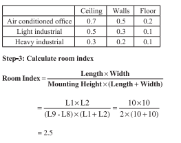
Step-2: Collect the room data in the format given below
Typical reflectance values for using in L5, L6, L7 are:
Step 4: Calculate the utilisation factor
Utilisation factor is defined as the percent of rated bare-lamp lumens that exit the luminaire and reach
the work plane. It accounts for light directly from the luminaire as well as light reflected off the room
surfaces. Manufacturers will supply each luminaire with its own CU table derived from a photometric
test report.
Using tables available from manufacturers, it is possible to determine the utilisation factor for different
light fittings if the reflectance of both the walls and ceiling is known, the room index has been determined
and the type of luminaire is known. For twin tube fixture, utilisation factor is 0.66, corresponding to
room index of 2.5.
Step-5: To calculate the number of fittings required, the following formula is used Where, MF = Maintenance Factor
Typical LLF values
A
So, 6 Numbers of Twin Tube Fixtures are required. Total number of 36 W lamp is 12. Step 6: Space the luminaires to achieve desired uniformity
Every luminaire will have a recommended space to height
ratio. In earlier design methodologies, the uniformity ratio,which is the ratio of minimum illuminance to average illuminance, was kept at 0.8 and suitable space to height
ratio is specified to achieve the uniformity. In modern
designs incorporating energy efficiency and task lighting, the emerging concept is to provide a uniformity of 1/3 to
1/10 depending on the tasks.
Recommended value for the above luminaire is 1.5. If the actual ratio is more than the recommended
values, the uniformity of lighting will be less.
For a sample of arrangement of fittings, refer Figure 8.14. The luminaire closer to a wall should be
one half of spacing or less.
Luminaire Spacing
Spacing between luminaires = 10/3 = 333m
Mounting height (L9-L8) = 2.0m
Space to height ratio (SHR) = 3.33/2.0 = 1.66
This is close to the limits specified and hence accepted.
It is better to choose luminaires with larger SHR. This can reduce the number of fittings and connected
lighting load.
General Energy Saving Opportunities
Changing the light bulbs is not the only way to improve the use of lighting. Below are some examples
of many other options available:
a) Use natural day lighting The utility of using natural day lighting instead of electric lighting during the day is well known, but
is being increasingly ignored especially in modern air-conditioned office spaces and commercial
establishments like hotels, shopping plazas etc. Industrial plants generally use daylight in some fashion,
but improperly designed day lighting systems can result in complaints from personnel or supplementary
use of electric lights during daytime.
Some of the methods to incorporate day lighting are:
i. North lighting by use if single-pitched truss of the saw-tooth type is a common industrial
practice; this design is suitable for latitudes north of 23 i.e. in North India. In South India,
north lighting may not be appropriate unless diffusing glasses are used to cut out the direct
sunlight.
il. Innovative designs are possible which eliminates the glare of daylight and blend well with
the interiors. Glass strips, running continuously across the breadth of the roof at regular
intervals, can provide good, uniform lighting on industrial shop floors and storage bays.
ill.A good design incorporating sky lights with FRP material along with transparent or translucent
false ceiling can provide good glare-free lighting; the false ceiling will also cut out the heat
that comes with natural light.
iV. Use of atrium with FRP dome in the basic architecture can eliminate the use of electric lights
in passages of tall buildings.
V.Natural Light from windows should also be used. However, it should be well designed to
avoid glare. Light shelves can be used to provide natural light without glare.
vi. Mounting Solar tube on the roof, with the help of advanced optics and special duct work to
direct sunlight deep into the buildings and spreading out over large internal spaces providing
heat and glare free daylighting for 8-10 hrs in a day.
b) De-lamping to reduce excess lighting
De-lamping is an effective method to reduce lighting energy consumption. In some industries, reducing
the mounting height of lamps, providing efficient luminaires and then de-lamping has ensured that the
illuminance is hardly affected. De-lamping at empty spaces where active work is not being performed
is also a useful concept.
c) Task lighting
Task Lighting implies providing the required good illuminance only in the actual small area where the
task is being performed, while the general illuminance of the shop floor or office is kept at a lower
level; e.g. Machine mounted lamps or table lamps. Energy saving takes place because good task lighting
can be achieved with low wattage lamps. The concept of task lighting if sensibly implemented, can
reduce the no of general lighting fixtures, reduce the wattage of lamps, save considerable energy and
provide better illuminance and also provide aesthetically pleasing ambience.
d) Selection of high efficiency lamps and luminaries
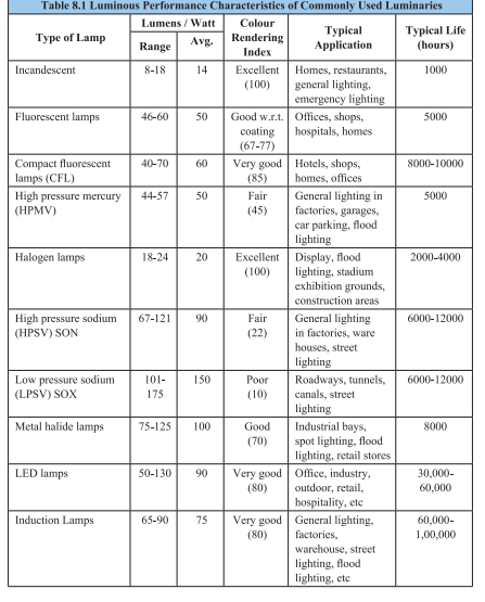
The details of common types of lamps are summarised in Table 8.1 above. It is possible to identify
energy saving potential for lamps by replacing with more efficient types. The following examples of
lamp replacements are common. There may be some limitations if colour rendering is an important
factor. It may be noted that, in most cases, the luminaires and the control gear would also have to be
changed. The savings are large if the lighting scheme is redesigned with higher efficacy lamps and
luminaires.
e) Reduction of lighting feeder voltage
Figure 8.15 shows the effect of variation of voltage on light output and power consumption for
fluorescent tube lights. Similar variations are observed on other gas discharge lamps like mercury
vapour lamps, metal halide lamps and sodium vapour lamps (Table 8.3 summarises the effects). Hence
reduction in lighting feeder voltage can save energy, provided the drop in light output is acceptable.
In many areas, night time grid voltages are higher than normal; hence reduction in voltage can save
energy and also provide the rated light output. Some manufacturers are supplying reactors and
transformers as standard products. A large number of industries have used these devices and have
reported saving to the tune of 5% to 15%. Industries having a problem of higher night time voltage
can get an additional benefit of reduced premature lamp failures.
f) Electronic ballasts
Conventional electromagnetic ballasts (chokes) are used to provide higher voltage to start the tube
light and subsequently limit the current during normal operation. Electronic ballasts are oscillators
that convert the supply frequency to about 20,000 Hz to 30,000 Hz. The basic functions of electronic
ballast are:
¢ To ignite the lamp
¢ To stabilize the gas discharge
¢ To supply the power to the lamp
The losses in electronic ballasts for tube lights are only about 1 Watt, in place of 10 to 15 Watts in
standard electromagnetic chokes.
The additional advantage is that the efficacy of tube lights improves at higher frequencies, resulting
in additional savings if the ballast is optimised to provide the same light output as with the conventional
choke. Hence a saving of about 15 to 20 Watts per tube light can be achieved by use of electronic
ballasts. With electronic ballast, the starter is eliminated and the tube light lights up instantly without
flickering.
g) Lighting controllers
Automatic control for switching off unnecessary lights can lead to good energy savings. This includes
dimmers, motion & occupancy sensors, photosensors and timers.
h) Lighting maintenance
Maintenance is vital to lighting efficiency. Light levels decrease over time because of aging lamps and
dirt on fixtures, lamps and room surfaces. Together, these factors can reduce total illumination by 50
percent or more, while lights continue drawing full power. The basic maintenance includes cleaning
of lamps and fixtures, cleaning and repainting interiors, relamping etc
Energy Efficient Lighting Controls
Occupancy Sensors
Occupancy-linked control can be achieved using infra-red, acoustic, ultrasonic or microwave sensors,
which detect either movement or noise in room spaces. These sensors switch lighting on when
occupancy is detected, and off again after a set time period, when no occupancy movement detected.
They are designed to override manual switches and to prevent a situation where lighting is left on in
unoccupied spaces. With this type of system it is important to incorporate a built-in time delay, since
occupants often remain still or quiet for short periods and do not appreciate being plunged into darkness
if not constantly moving around.
Timed Based Control
Timed-turnoff switches are the least expensive type of automatic lighting control. In some cases, their
low cost and ease of installation makes it desirable to use them where more efficient controls would
be too expensive.
Types and features
The oldest and most common type of timed-turnoff switch is the “dial timer,” a spring-wound mechanical
timer that is set by twisting the knob to the desired time. Typical units of this type are vulnerable to
damage because the shaft is weak and the knob is not securely attached to the shaft. Some spring wound units make an annoying ticking sound as they operate. Newer types of timed-turnoff switches
are completely electronic and silent. Electronic switches can be made much more rugged than the spring-wound dial timer. These units typically have a spring-loaded toggle switch that turns on the
circuit for a preset time interval. Some electronic models provide a choice of time intervals, which
you select by adjusting a knob located behind the faceplate. Most models allow occupants to turn off
the lights manually. Some models allow occupants to keep the lights on, overriding the timer. Timed�turnoff switches are available with a wide range of time spans. The choice of time span is a compromise.
Shorter time spans waste less energy but increase the probability that the lights will turn off while
someone is in the space. Dial timers allow the occupant to set the time span, but this is not likely to
be done with a view toward optimising efficiency. For most applications, the best choice is an electronic
unit that allows the engineering staff to set a fixed time interval behind the cover plate.
Daylight Linked Control
Photoelectric cells can be used either simply to switch lighting on and off, or for dimming. They may
be mounted either externally or internally. It is however important to incorporate time delays into the
control system to avoid repeated rapid switching caused, for example, by fast moving clouds. By using
an internally mounted photoelectric dimming control system, it is possible to ensure that the sum of
daylight and electric lighting always reaches the design level by sensing the total light in the controlled
area and adjusting the output of the electric lighting accordingly. If daylight alone is able to meet the
design requirements, then the electric lighting can be turned off. The energy saving potential of dimming
control is greater than a simple photoelectric switching system. Dimming control is also more likely
to be acceptable to room occupants.
Localized Switching
Localized switching should be used in applications which contain large spaces. Local switches give
individual occupants control over their visual environment and also facilitate energy savings. By using
localized switching it is possible to turn off artificial lighting in specific areas, while still operating it
in other areas where it is required, a situation which is impossible if the lighting for an entire space is
controlled from a single switch.
Street Lighting Systems and Controls
Street lighting /Public lighting is one of the major electrical loads in municipal areas. Number of street
lights used in a Municipal area varies from 20000 — 50000 in numbers depending on the kilometers
of road illuminated within the municipal limits. Typical electrical load of municipal lighting system
varies 2MW to 7 MW. The type of lamps used in Municipal area includes Fluorescent Tube light/
Mercury Vapor Lamps/ Sodium Vapor Lamps and Metal Halide Lamps. High Mast towers are also
used at strategic junctions in the Municipal area. LEDs are also used for traffic signaling purpose in
municipal areas.
Following controls are adopted to reduce energy consumption in street lighting system:
1. Timer control (Switch ON/OFF as per set timing)
2. Day light control(Based on illumination level)
3. Selective switching/Alternate switching of street lights low traffic density areas (after
midnight).
4. Switching control based on lux levels. (after midnight)
5. Installations of Voltage controllers to be operated after midnight.
6. Installation of PLC controlled Lighting panels for effective control and monitoring.
Standards and Labeling Programs for FTL Lamps
Considering the large number of fluorescent lamps (FTL) in usage, BEE has included FTL under
Standard and Labeling Programme (S&L). The S&L Programme covers 4 feet tubular fluorescent
lamps (101mm) for wattages up to 40W. The S&L programme includes 6500K colour temperature
for halo-phosphates and 6500K, 4000K & 2700K for tri-phosphate category. The star rating scheme
for FTL is given in Table 8.4.
Table 8.4 Star Rating scheme for FTL (101 mm)
Replacement of existing T12 Fluorescent lamps in street lighting system with LED lamps
Existing: Fluorescent lamp (T12) fixture of 40 numbers is connected to the entire campus for security
purpose. All the lights remain in operation for around 12 hours at night (6 p.m. to 6 am) every day
throughout the year. All the light fixtures are equipped with electromagnetic ballast which consumes
around 12 to 14 watt of additional power while in operation. Hence the power consumption of a single
fluorescent light fixture considering minimum ballast loss is 40+12=52 watts. The total light output
of all the fluorescent light fixtures is around 2400 lumen.
Proposed: It was proposed to replace existing lamps with high efficient LED lamps of 18 W with a
luminous efficacy of around 120-140 Im/w. The total luminous output of these lamps is around 2340
lumen.


Comments
Post a Comment