ENERGY_EFFICIENCY_IN_ELECTRICAL_UTILITIES
(Chapter 4:HVAC & Refrigiation system)
Introduction
The Heating, Ventilation and Air Conditioning (HVAC) and refrigeration system transfers the heat
energy from or to the products, or building environment. Energy in form of electricity or heat is used
to power mechanical equipment designed to transfer heat from a colder, low-energy level to a warmer,
high-energy level.
Refrigeration deals with the transfer of heat from a low temperature level at the heat source to a high temperature level at the heat sink by using a low boiling refrigerant.
There are several heat transfer loops in refrigeration system as described below:
In the Figure 4.1, thermal energy moves from left to right as it is extracted from the space and expelled into the outdoors through five loops of heat transfer:
— Indoor air loop. In the leftmost loop, indoor air is driven by the supply air fan through a cooling coil, where it transfers its heat to chilled water. The cool air then cools the building space.
— Chilled water loop. Driven by the chilled water pump, water returns from the cooling coil to the chiller’s evaporator to be re-cooled.
— Refrigerant loop. Using a phase-change refrigerant, the chiller’s compressor pumps heat from the chilled water to the condenser water.
— Condenser water loop. Water absorbs heat from the chiller’s condenser, and the condenser water pump sends it to the cooling tower.
— Cooling tower loop. The cooling tower’s fan drives air across an open flow of the hot condenser water, transferring the heat to the outdoors.
Psychrometrics and Air-Conditioning Processes
Psychrometrics is the science of moist air properties and processes, which is used to illustrate and analyze air-conditioning cycles. It translates the knowledge of heating or cooling loads (which are in kW or tons) into volume flow rates (in m2/s or cfm) for the air to be circulated into the duct system. Water vapor is lighter than dry air. The amount of water vapor that the air can carry increases with its temperature. Any amount of moisture that is present beyond what the air can carry at the prevailing temperature can only exist in the liquid phase as suspended liquid droplets (if the air temperature is above the freezing point of water), or in the solid state as suspended ice crystals (if the temperature is below the freezing point).
The most commonly used psychrometric quantities include the dry and wet bulb temperatures, dew point, specific humidity, relative humidity.
Psychrometric Chart:
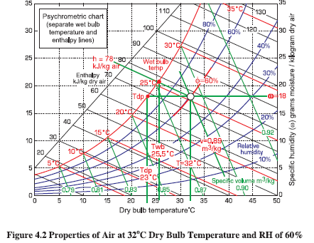
Psychrometric chart (Figure 4.2) is a chart indicating the psychrometric properties of air such as drybulb temperature, wet-bulb temperature, specific humidity, enthalpy of air in kJ/kg dry air, specific volume of air in m3/kg and relative humidity φ in %. It helps in quantifying and understanding air conditioning process.
Example: Assume that the outside air temperature is 32°C with a relative humidity of φ= 60%. Use the psychrometric chart to determine the air properties? See Figure 4.2.
Solution
Air properties of air at 32°C dry bulb temperature and RH of 60 %
Specific humidity = 18 gm-moisture/kg-air
Enthalpy h = 78kJ/kg-air
Wet-bulb temperature Twb = 25.5°C
Dew-point temperature Tdp = 23°C
The specific volume of the dry air v 0.89m37/kg
Comfort Zone
One of the major applications of the Psychrometric Chart is in air conditioning, and we find that most
humans feel comfortable when the temperature is between 22°C and 27°C, and the relative humidity
φbetween 40% and 60%. This defines the “comfort zone” which is portrayed on the Psychrometric
Chart as shown in Figure 4.3. Thus with the aid of the chart we either heat or cool, add moisture or
dehumidify as required in order to bring the air into the comfort zone.
Example 2:
Outside air at 35°C and 60% relative humidity is to be conditioned by cooling and reheating so as to bring the air to the “comfort zone” with the exit temperature of 24°C and 53% RH. Using the Psychrometric Chart neatly plot the required air conditioning process and estimate (a) the amount of moisture removed, (b) the heat removed, and (c) the amount of heat added. See Figure 4.3.

Ans: Using the Figure 4.3
(a) The amount of moisture removed = 11.5g-H,O /kg-dry-air
(b) The heat removed = (1)-(2), qcool = 48 kJ/kg-dry-air
(c) The amount of heat added = (2)-(3), qheat = 10 kJ/kg-dry-air
Air-Conditioning Systems
Depending on applications, there are several options / combinations, which are available for use as
given below:
¢ Air Conditioning (for comfort / machine)
e Split air conditioners
¢ Fan coil units in a larger system
e Air handling units in a larger system
Refrigeration Systems (for processes)
° Small capacity modular units of direct expansion type similar to domestic refrigerators, small capacity refrigeration units.
° Centralized chilled water plants with chilled water as a secondary coolant for temperature range over 5 °C typically. They can also be used for ice bank formation.
° Brine plants, which use brines as lower temperature, secondary coolant, for typically sub zero temperature applications, which come as modular unit capacities as well as large centralized plant capacities.
° The plant capacities upto 50 TR are usually considered as small capacity, 50 — 250 TR as medium capacity and over 250 TR as large capacity units.
A large industry may have a bank of such units, often with common chilled water pumps, condenser
water pumps, cooling towers, as an off site utility.
The same industry may also have two or three levels of refrigeration & air conditioning such as:
°Comfort air conditioning (20 — 25 °C)
° Chilled water system (8 — 10 °C)
° Brine system (sub-zero applications)
Two principle types of refrigeration plants found in industrial use are: Vapour Compression Refrigeration (VCR) and Vapour Absorption Refrigeration (VAR). VCR uses mechanical energy as the driving force for refrigeration, while VAR uses thermal energy as the driving force for refrigeration.
Types of Refrigeration System
Vapour Compression Refrigeration
Heat flows naturally from a hot to a colder body. In refrigeration system the opposite must occur i.e. heat flows from a cold to a hotter body. This is achieved by using a substance called a refrigerant,which absorbs heat and hence boils or evaporates at a low pressure to form a gas. This gas is then compressed to a higher pressure, such that it transfers the heat it has gained to ambient air or water and turns back (condenses) into a liquid. In this way heat is absorbed, or removed, from a low temperature source and transferred to a higher temperature source.
The refrigeration cycle can be broken down into the following stages (see Figure 4.4):
1-2 Low pressure liquid refrigerant in the evaporator absorbs heat from its surroundings, usually air, water or some other process liquid. During this process it changes its state from a liquid to a gas, and at the evaporator exit is slightly superheated.
2-3 The superheated vapour enters the compressor where its pressure is raised. There will also be a big increase in temperature, because a proportion of the energy input into the compression process is transferred to the refrigerant.
3-4 The high pressure superheated gas passes from the compressor into the condenser. The initial part of the cooling process (3 - 3a) desuperheats the gas before it is then turned back into liquid (3a - 3b). The cooling for this process is usually achieved by using air or water. A further reduction in temperature happens in the pipe work and liquid receiver (3b - 4), so that the refrigerant liquid is sub-cooled as it enters the expansion device.
4-1 The high-pressure sub-cooled liquid passes through the expansion device, which both reduces its pressure and controls the flow into the evaporator.

It can be seen that the condenser has to be capable of rejecting the combined heat inputs of the evaporator and the compressor; i.e. (1 - 2) + (2 - 3) has to be the same as (3 - 4). There is no heat loss or gain through the expansion device.
Absorption Refrigeration
The absorption chiller is a machine, which produces chilled water by using heat such as steam,hotwater, gas, oil etc. Chilled water is produced by the principle that liquid (refrigerant), which evaporates at low temperature, absorbs heat from surrounding when it evaporates. Pure water is used as refrigerant and lithium bromide solution is used as absorbent
Heat for the vapour absorption refrigeration system can be provided by waste heat extracted from process, diesel generator sets etc. Absorption systems require electricity to run pumps only. Depending
on the temperature required and the power cost, it may even be economical to generate heat / steam to operate the absorption system.
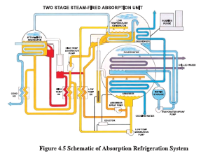
Description of the absorption refrigeration concept is given below:


A typical schematic of the absorption refrigeration system is given in the Figure 4.5. Li-Br-water absorption refrigeration systems have a Coefficient of Performance (COP) in the range of 0.65 - 0.70 and can provide chilled water at 6.7 °C with a cooling water temperature of 30 °C. Systems capable of providing chilled water at 3 °C are also available. Ammonia based systems operate at above atmospheric pressures and are capable of low temperature operation (below 0°C). Absorption machines of capacities in the range of 10-1500 tons are available. Although the initial cost of absorption system is higher than compression system, operational cost is much lower-if waste heat is used.
Evaporative Cooling
There are occasions where air conditioning, which stipulates control of humidity up to 50 % for human comfort or for process, can be replaced by a much cheaper and less energy intensive evaporative cooling.
The concept is very simple and is the same as that used in a cooling tower. Air is brought in close contact with water to cool it to a temperature close to the wet bulb temperature. The cool air can be used for comfort or process cooling. The disadvantage is that the air is rich in moisture. Nevertheless, it is an extremely efficient means of cooling at very low cost. Large commercial systems employ cellulose filled pads over which water is sprayed. The temperature can be controlled by controlling the airflow and the water circulation rate. The possibility of evaporative cooling is especially attractive for comfort cooling in dry regions. This principle is practiced in textile industries for certain processes.
Common Refrigerants and Properties
A variety of refrigerants are used in vapor compression systems. The choice of fluid is determined largely by the cooling temperature required. Commonly used refrigerants are in the family of chlorinated fluorocarbons (CFCs, also called Freons): R-11, R-12, R-21, R-22 and R-502. The properties of these refrigerants are summarized in Table 4.1 and the performance of these refrigerants is given in Table 4.2.
The choice of refrigerant and the required cooling temperature and load determine the choice of compressor, as well as the design of the condenser, evaporator, and other auxiliaries. Additional factors such as ease of maintenance, physical space requirements and availability of utilities for auxiliaries (water, power, etc.) also influence component selection.
Compressor Types and Application
For industrial use, open type systems (compressor and motor as separate units) are normally used, though hermetic systems (motor and compressor in a sealed unit) also find service in some low capacity
applications. Hermetic systems are used in refrigerators, air conditioners, and other low capacity applications. Industrial applications largely employ reciprocating, centrifugal and, more recently, screw
compressors, and scroll compressors. Water-cooled systems are more efficient than air-cooled alternatives because the temperatures produced by refrigerant condensation are lower with water than with air.
Centrifugal Compressors
Centrifugal compressors are the most efficient type (see Figure 4.6) when they are operating near full
load. Their efficiency advantage is greatest in large sizes, and they offer considerable economy of scale, so they dominate the market for large chillers. They are able to use a wide range of refrigerants efficiently, so they will probably continue to be the dominant type in large sizes.
Centrifugal compressors have a single major moving part - an impeller that compresses the refrigerant gas by centrifugal force. The gas is given kinetic energy as it flows through the impeller. This kinetic energy is not useful in itself, so 1t must be converted to pressure energy. This is done by allowing the gas to slow down smoothly in a stationary diffuser surrounding the impeller. To minimize efficiency loss at reduced loads, centrifugal compressors typically throttle output with inlet guide vanes located at the inlet to the impeller(s). This method is efficient down to about 50% load, but the efficiency of this method decreases rapidly below 50% load.
Older centrifugal machines are not able to reduce load much below 50%. This is because of “surge” in the impeller. As the flow through the impeller is choked off, the gas does not acquire enough energy to overcome the discharge pressure. Flow drops abruptly at this point, and an oscillation begins as the gas flutters back and forth in the impeller. Efficiency drops abruptly, and the resulting vibration can damage the machine. Many older centrifugal machines deal with low loads by creating a false load on the system, such as by using hot gas bypass. This wastes the portion of the cooling output that is not required.
Another approach is to use variable-speed drives in combination with inlet guide vanes. This may
allow the compressor to throttle down to about 20% of full load, or less, without false loading. Changing the impeller speed causes a departure from optimum performance, so efficiency still declines badly at low loads. A compressor that uses a variable-speed drive reduces its output in the range between full load and approximately half load by slowing the impeller speed. At lower loads, the impeller cannot be slowed further, because the discharge pressure would become too low to condense the refrigerant.Below the minimum load provided by the variable-speed drive, inlet guide vanes are used to provide further capacity reduction.
Reciprocating Compressors
The maximum efficiency of reciprocating compressors (see Figure 4.7) is lower than that of centrifugal and screw compressors. Efficiency is reduced by clearance volume (the compressed gas volume that is left at the top of the piston stroke), throttling losses at the intake and discharge valves, abrupt changes in gas flow, and friction. Lower efficiency also results from the smaller sizes of reciprocating units, because motor losses and friction account for a larger fraction of energy input in smaller systems.
Reciprocating compressors suffer less efficiency loss at partial loads than other types, and they may actually have a higher absolute efficiency at low loads than the other types. Smaller reciprocating compressors control output by turning on and off. This eliminates all part-load losses, except for a short period of inefficient operation when the machine starts.
Larger multi-cylinder reciprocating compressors commonly reduce output by disabling (“unloading’’) individual cylinders. When the load falls to the point that even one cylinder provides too much capacity,
the machine turns off. Several methods of cylinder unloading are used, and they differ in efficiency. The most common is holding open the intake valves of the unloaded cylinders. This eliminates most of the work of compression, but a small amount of power is still wasted in pumping refrigerant gas to-and-fro through the unloaded cylinders. Another method is blocking gas flow to the unloaded cylinders, which is called “suction cutoff.”
Variable-speed drives can be used with reciprocating compressors, eliminating the complications of cylinder unloading. This method is gaining popularity with the drastic reduction in costs of variable speed drives.
Screw Compressors
Screw compressors, sometimes called “helical rotary” compressors compress refrigerant by trapping it in the “threads” of a rotating screw-shaped rotor (see Figure 4.8). Screw compressors have increasingly taken over from reciprocating compressors of medium sizes and large sizes, and they have even entered the size domain of centrifugal machines. Screw compressors are applicable to refrigerants that have higher condensing pressures, such as HCFC-22 and ammonia. They are especially compact. A variety of methods are used to control the output of screw compressors. There are major efficiency differences among the different methods. The most common is a slide valve that forms a portion of the housing that surrounds the screws.

Using a variable-speed drive is another method of capacity control. It is limited to oil-injected compressors, because slowing the speed of a dry compressor would allow excessive internal leakage. There are other methods of reducing capacity, such as suction throttling that are inherently less efficient
than the previous two.
Scroll Compressors
The scroll compressor is an old invention that has finally come to the market. The gas is compressed between two scroll-shaped vanes. One of the vanes is fixed, and the other moves within it. The moving vane does not rotate, but its center revolves with respect to the center of the fixed vane, as shown in Figure 4.9. This motion squeezes the refrigerant gas along a spiral path, from the outside of the vanes
toward the center, where the discharge port is located. The compressor has only two moving parts, the moving vane and a shaft with an offcenter crank to drive the moving vane. Scroll compressors have only recently become practical, because close machining tolerances are needed to prevent leakage between the vanes, and between the vanes and the casing. The features of various refrigeration compressors and application criteria are given in the Table 4.3.

Selection of a Suitable Refrigeration System
A clear understanding of the cooling load to be met is the first and most important part of designing / selecting the components of a refrigeration system. Important factors to be considered in quantifying the load are the actual cooling need, heat (cool) leaks, and internal heat sources (from all heat generating equipment). Consideration should also be given to process changes and / or changes in ambient conditions that might affect the load in the future. Reducing the load, e.g. through better insulation, maintaining as high a cooling temperature as practical, etc. is the first step toward minimizing electrical power required to meet refrigeration needs. With a quantitative understanding of the required temperatures and the maximum, minimum, and average expected cooling demands, selection of appropriate refrigeration system (single-stage / multi-stage, economized compression, compound / cascade operation, direct cooling / secondary coolants) and equipment (type of refrigerant, compressor, evaporator, condenser, etc.) can be undertaken.
Performance Assessment of Refrigeration Plants
The cooling effect produced is quantified as tons of refrigeration.(TR).
1 TR of refrigeration = 3024 kcal/hr heat rejected.
The refrigeration TR is assessed as
Where,
Q is mass flow rate of coolant in kg/hr
Cp is coolant specific heat in kcal /kg deg °C
Ti is inlet, temperature of coolant to evaporator (chiller) in °C
To is outlet temperature of coolant from evaporator (chiller) in °C
The above TR is also called as chiller tonnage.
The specific power consumption kW/TR is a useful indicator of the performance of refrigeration system. By measuring refrigeration duty performed in TR and the kiloWatt inputs, kW/TR is used as
a reference energy performance indicator.
In a centralized chilled water system, apart from the compressor unit, power is also consumed by the chilled water (secondary) coolant pump as well condenser water (for heat rejection to cooling tower)
pump and cooling tower fan in the cooling tower. Effectively, the overall energy consumption would
be towards:
- Compressor kW
- Chilled water pump kW
- Condenser water pump kW
- Cooling tower fan kW, for induced / forced draft towers
The specific power consumption for certain TR output would therefore have to include:
- Compressor kW/TR
- Chilled water pump kW/TR
- Condenser water pump kW/TR
- Cooling tower fan kW/TR
The overall kW/TR is the sum of the above.
The theoretical Coefficient of Performance (Carnot), COP carnot- a standard measure of refrigeration efficiency of an ideal refrigeration system- depends on two key system temperatures, namely, evaporator temperature Tc and condenser temperature Tc with COP being given as:
COP crnot= Tc / (Tc-Te)
This expression also indicates that higher COPcarnot is achieved with higher evaporator temperature and lower condenser temperature.
But COPcarnot 1S only a ratio of temperatures, and hence does not take into account the type of compressor.
Hence the COP normally used in the industry is given by

Where the cooling effect is the difference in enthalpy across the evaporator and expressed as kW. The effect of evaporating and condensing temperatures are given in the Figure 4.10 and Figure 4.11 below:

In the field performance assessment, accurate instruments for inlet and outlet chilled water temperature and condenser water temperature measurement are required, preferably with a least count of 0.1°C. Flow measurements of chilled water can be made by an ultrasonic flow meter directly or inferred from pump duty parameters. Adequacy check of chilled water is needed often and most units are designed for a typical 0.68 m*/hr per TR (3 gpm/TR) chilled water flow. Condenser water flow measurement can also be made by a non-contact flow meter directly or inferred from pump duty parameters. Adequacy check of condenser water is also needed often, and most units are designed for a typical 0.91 m3/hr per TR (4 gpm / TR) condenser water flow.
In case of air conditioning units, the airflow at the Fan Coil Units (FCU) or the Air Handling Units (AHU) can be measured with an anemometer. Dry bulb and wet bulb temperatures are measured at the inlet and outlet of AHU or the FCU and the refrigeration load in TR is assessed as ;

hin is enthalpy of inlet air kcal/kg
hout 1s enthalpy of outlet air kcal/kg
Use of psychometric charts can help to calculate hin and hout from dry bulb, wet bulb temperature values which are, in-turn measured, during trials, by a whirling psychrometer.
Power measurements at, compressor, pumps, AHU fans, cooling tower fans can be accomplished by a portable load analyzer.
Estimation of air conditioning load is also possible by calculating various heat loads, sensible and latent based on inlet and outlet air parameters, air ingress factors, air flow, no. of people and type of materials stored.
An indicative TR load profile for air conditioning is presented as follows:
° Small office cabins = 0.1 TR /m2
° Medium size office i.e.,
10 — 30 people occupancy
with central A/C = 0.06 TR/ m2
° Large multistoried office
complexes with central A/C = 0.04 TR/ m2
Integrated Part Load Value (IPLV)
Although the kW/ TR can serve as an initial reference, it should not be taken as an absolute since this value is derived from 100% of the equipment’s capacity level and is based on design conditions that are considered the most critical. These conditions occur may be, for example, during only 1% of the total time the equipment is in operation throughout the year. Consequently, it is essential to have data that reflects how the equipment operates with partial loads or in conditions that demand less than 100% of its capacity. To overcome this, an average of kW/TR with partial loads ie Integrated Part Load Value (IPLV) have to be formulated.
The IPLV is the most appropriate reference, although not considered the best, because it only captures four points within the operational cycle: 100%, 75%, 50% and 25%. Furthermore, it assigns the same weight to each value, and most equipment usually operates at between 50 % and 75% of its capacity. This is why it is so important to prepare specific analysis for each case that addresses the four points already mentioned, as well as developing a profile of the heat exchanger’s operations during the year.
Factors Affecting Performance & Energy Efficiency of Refrigeration Plants
Design of Process Heat Exchangers
There is a tendency of the process group to operate with high safety margins which influences the compressor suction pressure / evaporator set point. For instance, a process cooling requirement of 15°C would need chilled water at a lower temperature, but the range can vary from 6°C to say 10°C. At 10°C chilled water temperature, the refrigerant side temperature has to be lower, say —5°C to +5°C.The refrigerant temperature, again sets the corresponding suction pressure of refrigerant which decides the inlet duty conditions for work of compression of the refrigerant compressor. Having the optimum/ minimum driving force (temperature difference) can, thus, help to achieve highest possible suction pressure at the compressor, thereby leading to less energy requirement. This requires proper sizing of heat transfer areas of process heat exchangers and evaporators as well as rationalizing the temperature requirement to highest possible value. A 1°C raise in evaporator temperature can help to save almost 3 % on power consumption. The TR capacity of the same machine will also increase with the evaporator temperature, as given in Table 4.4.

Towards rationalizing the heat transfer areas, the heat transfer coefficient on refrigerant side can be
considered to range from 1400 — 2800 watts /m2K.
The refrigerant side heat transfer areas provided are of the order of 0.5 Sqm./TR and above in
evaporators.
Condensers in a refrigeration plant are critical equipment that influences the TR capacity and power consumption demands. Given a refrigerant, the condensing temperature and corresponding condenser pressure, depend upon the heat transfer area provided, effectiveness of heat exchange and the type of cooling chosen. A lower condensing temperature, pressure, in best of combinations would mean that the compressor has to work between a lower pressure differential as the discharge pressure is fixed by design and performance of the condenser. The choices of condensers in practice range from air cooled, air cooled with water spray, and heat exchanger cooled. Generously sized shell and tube heat exchangers as condensers, with good cooling tower operations help to operate with low discharge pressure values and the TR capacity of the refrigeration plant also improves. With same refrigerant, R22, a discharge pressure of 15 kg/cm2 with water cooled shell and tube condenser and 20 kg/cm2 with air cooled condenser indicate the kind of additional work of compression duty and almost 30 % additional energy consumption required by the plant. One of the best option at design stage would be to select generously sized (0.65 m?/TR and above) shell and tube condensers with water-cooling as against cheaper alternatives like air cooled condensers or water spray atmospheric condenser units.
The effect of condenser temperature on refrigeration plant energy requirements is given in Table 4.5.

Maintenance of Heat Exchanger Surfaces
After ensuring procurement, effective maintenance holds the key to optimizing power consumption. Heat transfer can also be improved by ensuring proper separation of the lubricating oil and the refrigerant, timely defrosting of coils, and increasing the velocity of the secondary coolant (air, water,
etc.). However, increased velocity results in larger pressure drops in the distribution system and higher
power consumption in pumps / fans. Therefore, careful analysis is required to determine the most
effective and efficient option.
Fouled condenser tubes force the compressor to work harder to attain the desired capacity. For example,
a 0.8 mm scale build-up on condenser tubes can increase energy consumption by as much as 35 %. Similarly, fouled evaporators (due to residual lubricating oil or infiltration of air) result in increased power consumption. Equally important is proper selection, sizing, and maintenance of cooling towers. A reduction of 0.55°C temperature in water returning from the cooling tower reduces compressor power
consumption by 3.0 % (see Table 4.6).

Multi-Staging for Efficiency
Efficient compressor operation requires that the compression ratio be kept low, to reduce discharge pressure and temperature. For low temperature applications involving high compression ratios, and for wide temperature requirements, it is preferable (due to equipment design limitations) and often economical to employ multi-stage reciprocating machines or centrifugal / screw compressors. Multi-staging systems are of two-types: compound and cascade — and are applicable to all types of compressors. With reciprocating or rotary compressors, two-stage compressors are preferable for load temperatures from —20 to —58°C, and with centrifugal machines for temperatures around —43°C. In multi-stage operation, a first-stage compressor, sized to meet the cooling load, feeds into the suction of a second-stage compressor after inter-cooling of the gas. A part of the high-pressure liquid from the condenser is flashed and used for liquid sub-cooling. The second compressor, therefore, has to meet the load of the evaporator and the flash gas. A single refrigerant is used in the system, and the work of compression is shared equally by the two compressors. Therefore, two compressors with low compression ratios can in combination provide a high compression ratio.
For temperatures in the range of —-46°C to —101°C, cascaded systems are preferable. In this system, two separate systems using different refrigerants are connected such that one provides the means of heat rejection to the other. The chief advantage of this system is that a low temperature refrigerant which has a high suction temperature and low specific volume can be selected for the low-stage to meet very low temperature requirements.
Matching Capacity to System Load
During part-load operation, the evaporator temperature rises and the condenser temperature falls, effectively increasing the COP. But at the same time, deviation from the design operation point and the fact that mechanical losses form a greater proportion of the total power negate the effect of improved COP, resulting in lower part-load efficiency.
Therefore, consideration of part-load operation is important, because most refrigeration applications have varying loads. The load may vary due to variations in temperature and process cooling needs. Matching refrigeration capacity to the load is a difficult exercise, requiring knowledge of compressor performance, and variations in ambient conditions, and detailed knowledge of the cooling load.
Capacity Control and Energy Efficiency
The capacity of compressors is controlled in a number of ways. Capacity control of reciprocating compressors through cylinder unloading results in incremental (step-by-step) modulation as against continuous capacity modulation of centrifugal through vane control and screw compressors through sliding valves. Therefore, temperature control requires careful system design. Usually, when using reciprocating compressors in applications with widely varying loads, it is desirable to control the compressor by monitoring the return water (or other secondary coolant) temperature rather than the temperature of the water leaving the chiller. This prevents excessive on-off cycling or unnecessary loading / unloading of the compressor. However, if load fluctuations are not high, the temperature of the water leaving the chiller should be monitored. This has the advantage of preventing operation at very low water temperatures, especially when flow reduces at low loads. The leaving water temperature should be monitored for centrifugal and screw chillers.
Capacity regulation through speed control is the most efficient option. However, when employing speed control for reciprocating compressors, it should be ensured that the lubrication system is not affected. In the case of centrifugal compressors, it is usually desirable to restrict speed control to about50 % of the capacity to prevent surging. Below 50 %, vane control or hot gas bypass can be used for capacity modulation.
The efficiency of screw compressors operating at part load is generally higher than either centrifugal compressors or reciprocating compressors, which may make them attractive in situations where partload
operation is common. Screw compressor performance can be optimized by changing the volume ratio. In some cases, this may result in higher full-load efficiencies as compared to reciprocating and centrifugal compressors. Also, the ability of screw compressors to tolerate oil and liquid refrigerant
slugs makes them preferred in some situations.
Multi-level Refrigeration for Plant Needs
The selection of refrigeration systems also depends on the range of temperatures required in the plant. For diverse applications requiring a wide range of temperatures, it is generally more economical to
provide several packaged units (several units distributed throughout the plant) instead of one large
central plant. Another advantage would be the flexibility and reliability accorded. The selection of
packaged units could also be made depending on the distance at which cooling loads need to be met.
Packaged units at load centers reduce distribution losses in the system. Despite the advantages of
packaged units, central plants generally have lower power consumption since at reduced loads power
consumption can reduce significantly due to the large condenser and evaporator surfaces.
Many industries use a bank of compressors at a central location to meet the load. Usually the chillers
feed into a common header from which branch lines are taken to different locations in the plant. In
such situations, operation at part-load requires extreme care. For efficient operation, the cooling load,
and the load on each chiller must be monitored closely. It is more efficient to operate a single chiller
at full load than to operate two chillers at part-load. The distribution system should be designed such
that individual chillers can feedall branch lines. Isolation valves must be provided to
ensure that chilled water (or other coolant) does not flow through — chillers not in
operation. Valves should also be provided on branch lines to isolate sections where cooling is not
required. This reduces pressure drops in the system and reduces power consumption in the pumping
system. Individual compressors should be loaded to their full capacity before operating the second
compressor. In some cases it is economical to provide a separate smaller capacity chiller, which can
be operated on an on-off control to meet peak demands, with larger chillers meeting the base load.
Flow control is also commonly used to meet varying demands. In such cases the savings in pumping
at reduced flow should be weighed against the reduced heat transfer in coils due to reduced velocity.
In some cases, operation at normal flow rates, with subsequent longer periods of no-load (or shut-off)
operation of the compressor, may result in larger savings.
Chilled Water Storage
Depending on the nature of the load, it is economical to provide a chilled water storage facility with
very good cold insulation. Also, the storage facility can be fully filled to meet the process requirements
so that chillers need not be operated continuously. This system is usually economical if small variations
in temperature are acceptable. This system has the added advantage of allowing the chillers to be
operated at periods of low electricity demand to reduce peak demand charges - Low tariffs offered by
some electric utilities for operation at night time can also be taken advantage of by using a storage
facility. An added benefit is that lower ambient temperature at night lowers condenser temperature
and thereby increases the COP.
If temperature variations cannot be tolerated, it may not be economical to provide a storage facility
since the secondary coolant would have to be stored at a temperature much lower than required to
provide for heat gain. The additional cost of cooling to a lower temperature may offset the benefits.
The solutions are case specific. For example, in some cases it may be possible to employ large heat
exchangers, at a lower cost burden than low temperature chiller operation, to take advantage of the
storage facility even when temperature variations are not acceptable. Ice bank systems which store
ice rather than water are often economical.
System Design Features
In overall plant design, adoption of good practices improves the energy efficiency significantly. Some
areas for consideration are:
° Design of cooling towers with FRP impellers and film fills, PVC drift eliminators, etc.
° Use of softened water for condensers in place of raw water.
° Use of economic insulation thickness on cold lines, heat exchangers, considering cost of heat gains and adopting practices like infrared thermography for monitoring - applicable especially in large chemical / fertilizer / process industry.
° Adoption of roof coatings / cooling systems, false ceilings / as applicable, to minimize refrigeration load.
° Adoption of energy efficient heat recovery devices like air to air heat exchangers to pre-cool the fresh air by indirect heat exchange; control of relative humidity through indirect heat exchange rather than use of duct heaters after chilling.
° Adopting of variable air volume systems; adopting of sun film application for heat reflection; optimizing lighting loads in the air conditioned areas; optimizing number of air changes in the air conditioned areas are few other examples.
Performance Assessment of window, split and package air conditioning units
Air Conditioners
Energy Efficiency Ratio (EER): EER is calculated by dividing a chiller’s cooling capacity (in watts)
by its power input (in watts) at full-load conditions. This definition of EER has been adopted in BEE
star labeling programme.
The energy efficiency ratio (EER) = Refrigeration effect in Watts/ Power input in Watts
Based on the condition of the air, the air properties such as specific volume and enthalpy at both inlet
and out let conditions can be obtained from psychrometric charts. From these parameters the capacity
delivered by the air conditioner can be evaluated, which when compared with power drawn would
reveal its performance in terms of kW/TR and EER.
Performance Assessment of Package Air Conditioner — Example
Package air conditioner capacity - 10 TR
Average Air Velocity - 2.27 m/s (across suction side filter)
Cross Sectional Area - 0.58 m2
Air Flow Rate - 1.32 m3/sec - 4751 m3/hr
Inlet Air Condition
DBT - 20 °C
WBT - 14°
Sp. Vol - 0.8405 m3/kg
Enthalpy - 9.37 kcal/kg
Outlet Air Condition
DBT - 12.7°C
WBT - 11.3 °C
Enthalpy - 7.45 kcal/kg
Cooling Effect Delivered -3.6TR =12.7kW
Power Drawn
Compressor - 4.71kW
- 4.3 kW (shaft power@ 90% motor efficiency)
Pump - 2.14kW
C.T Fan - 0.384kW
Specific Energy Consumption
Compressor - 1.31 kW/TR
Overall - 2 kW/TR
EER - 12700/4300
- 2.95 W/W
Note: The Package A/C unit has two compressors of 5 TR capacity each, of which only one was in
operation due to low cooling load.
Cold Storage Systems
A Refrigerated storage which includes cold storage and frozen food storage is the best known method
of preservation of food to retain its value and flavor.
The refrigeration system in a cold storage is usually a vapour compression system comprising the
compressor, condenser, receiver, air cooling units and associate piping and controls.
In smaller cold rooms and walk-ins the practice is to use air cooled condensing units with sealed,
semi-sealed or open type compressors. In the light of the CFC phase out the trend now is to use HCFC-
22, HFC-134a or other substitute refrigerants. In the medium and large sized units the practice is to
use a central plant with ammonia as the refrigerant.
In some present day medium and large sized units with pre-fabricated (insulated) panel construction
the trend is to use modular HCFC-22/HFC units which are compact, light weight and easy to maintain.
Energy Saving Opportunities in Cold Storage Systems:
Energy cost constitutes a major part of the running cost of a cold store. Apart from the problems of
the availability of electrical energy, the ever increasing rate of electrical energy seriously affects the
economic viability of cold store units.
Following are some of the measures adopted to achieve energy efficient operation.
° Cold Store Building Design: Proper orientation, compact arrangement of chambers, shading of exposed walls, adequate insulation etc. are some of the important factors.
. Refrigeration System: The system must be designed for optimum operating conditions like evaporating and condensing temperatures, as these conditions have a direct bearing on energy consumption.
° Compressor capacity control system helps in energy savings during partial load operation.
° Control System: The proper control systems for refrigerant level, room temperature,
compressor capacity etc., are required to further optimize energy consumption.
° Air Curtain or Strip Curtain: The use of air curtains and strip curtains is a common feature in present day cold stores as they help reduce air infiltration due to frequent and some times long door openings. Fan operated air curtains are expensive and work on electrical power whereas strip curtains are cheaper and need no energy for operation.
° Heat Recovery System: In processing plant cold stores, a heat reclaim system can be installed to recover a part of the heat rejected by the refrigeration system. This can be gainfully utilised
in generating hot water free of cost.
Heat Pumps and Their Applications
Heat Pump Technology
A heat pump is same as an air conditioner except that the heat rejected in an air conditioner becomes the useful heat output. Heat flows naturally from a higher to a lower temperature. Heat pumps, however, are able to force the heat flow in the other direction, using a relatively small amount of high quality drive energy (electricity, fuel, or hightemperature waste heat). For the example shown in 4.12 the heat pump takes three units of energy from atmosphere and with an additional one unit by way of compressor work is able to provide four units of energy at a higher temperature.Thus heat pumps can transfer heat from natural heat sources in the surroundings, such as the air, ground or water, or from man-made heat sources such as industrial or domestic waste, to a building or an industrial application.
In order to transport heat from a heat source to a heat sink, external energy is needed to drive the heat
pump. Theoretically, the total heat delivered by the heat pump is equal to the heat extracted from the
heat source, plus the amount of drive energy supplied. Electrically-driven heat pumps for heating
buildings typically supply 100 kWh of heat with just 20-40 kWh of electricity. Many industrial heat
pumps can achieve even higher performance, and supply the same amount of heat with only 3-10 kWh
of electricity. The principle of operation of heat pump is shown in the Figure 4.13.
Heat Pump Applications
Industrial heat pumps are mainly used for:
1.Space heating
2.Heating of process streams
3.Water heating for washing, sanitation and cleaning
4.Steam production
5.Drying/dehumidification
6.Evaporation
7.Distillation
8.Concentration
When heat pumps are used in drying, evaporation and distillation processes, heat is recycled within
the process. For heating of the space, process streams and steam production, the heat pumps utilise
(waste) heat sources between 20°C and 100°C.
Ventilation Systems
Ventilation can be simply described as air circulation, the extraction of stale, overheated and contaminated air and supply and distribution of fresh air in amounts necessary to provide healthy and
comfortable conditions for the occupants of the room. The ventilation effectiveness is dictated by
number of Air Changes per Hour (ACH). The number air changes depend on the purpose and function.
Typical air changes are given in Table 4.7 for various operations.
Calculation of ventilation rate: If the compressor room size is 15 m(L) X 10 m (B) X 4 m (H) then
the ventilation rate is
=LxBXHXACH
=15X10X4X1 0
= 6000 m3/hr
Ice Bank Systems
Ice Bank System is a proven technology that has been utilized for decades Thermal energy storage
takes advantage of low cost, off-peak electricity, produced more efficiently throughout the night, to
create and store cooling energy for use when electricity tariffs are higher, typically during the day.
There are full- and partial- load Off-Peak Cooling systems. The essential element for either full- or
partial- storage configurations are thermal- energy storage tanks. Each tank contains a spiral-wound,
polyethylene-tube heat exchanger surrounded with water. ICEBANK tanks are available in a variety
of sizes ranging from 45 to over 500 ton-hours. These systems are economical based on the electricity
tariff of particular utility. These systems can be employed to meet the air conditioning requirements
in the commercial buildings as well as to meet the chilling requirements in Diary and process industry.
The main advantage of these systems is to reduce the peak demand of the utility and also reduce the
cost of operation for the end user
How Ice Bank Works?
With a partial-storage system, the chiller can be 40 to 50 percent smaller than other HVAC systems,
because the chiller works in conjunction with the ICEBANK tanks during on-peak daytime hours to
manage the building’s cooling load. During off-peak night time hours, the chiller charges the ICEBANK tanks for use during the next day’s cooling. The lowest possible average load is obtained by extending the chiller hours of operation.
Humidification Systems
This is a process involving reduction in dry bulb temperature and increase in specific humidity. The
atmospheric conditions with respect to humidity play a very important part in many manufacturing
processes. For example in textile processing the properties like dimensions, weight, tensile strength, elastic
recovery, electrical resistance, rigidity etc. of all textile fibre are influenced by humidity maintained.
Temperature does not have a great effect on the fibres but the temperature dictates the amount of
moisture the air will hold in suspension and, therefore, temperature and humidity must be considered
together. Humidification system without chilling helps to maintain only the RH% without much
difficulty.
Adiabatic saturation or evaporative cooling
In this process (Figure 4.14) air comes in direct contact with water in the air washer. There is heat and
mass transfer between air and water. The humidity ratio of air increases. If the time of contact is
sufficient, the air gets saturated. Latent heat of evaporation required for conversion of water into water
vapor is taken from the remaining water. When equilibrium conditions are reached, water cools down
to the wet bulb temperature of the air. If the air washer is ideal, the dry bulb temperature and wet bulb
temperature of the air would be equal. Dry bulb temperature of the air goes down in the process and
the effect of cooling is due to the evaporation of some part of the water. That is why it is called
Evaporative Cooling.
The sensible heat is decreased as the temperature goes down but the latent heat goes up as water vapour
is added to the air. The latent heat required by the water which is evaporated in the air is drawn from the sensible heat of the same air.Thus it is transformation of sensible heat to latent heat. During this: process the enthalpy of air remains the same. If humidity ratios of saturated air and of the air before saturation are known, then the difference between the two would be the amount of water vapour absorbed by unit. weight of dry air.
Humidifying Air by adding Water
If water is added to air without any heat supply the state of air change adiabatic along a constant enthalpy line in the psychrometric chart. The dry bulb temperature of the air decreases.
The amount of added water can be expressed as

Example - Humidifying Air by adding Water
In an air washer of textile humidification system airflow of 3000 m3/h at 25°C and 10% relative humidity is humidified to 60% relative humidity by adding water through spray nozzles. Calculate the amount of water required. The specific humidity of air at inlet and outlet are 0.002 kg/kg and 0.0062 kg/kg respectively.
Solution
The amount of water added can be calculated as:
mw= 3000 X 1.184 X (0.0062 0.002)
= 14.9 kg/h
Standards and Labeling of Room Air Conditioners
This Standard specifies the energy labeling requirements for single-phase split and unitary air conditioners of the vapour compression type for household use up to a rated cooling capacity of 11 kW and that fall within the scope of IS1391 Part 1 and Part 2, being manufactured, imported, or sold in India.
The number of stars displayed on the energy label. The available stars are between a minimum of one
and a maximum of five shown in one star interval. The star rating is calculated from the Star Rating
Band.
The Table 4.8 & 4.9 below is valid for split and unitary type air conditioners between 01 January 2014
and 31‘ December 2015.
Energy Saving Opportunities
a) Cold Insulation
Insulate all cold lines / vessels using economic insulation thickness to minimize heat gains; and choose appropriate (correct) insulation.
b) Building Envelope
Optimise air conditioning volumes by measures such as use of false ceiling and segregation of critical areas for air conditioning by air curtains.
c) Building Heat Loads Minimisation
Minimise the air conditioning loads by measures such as roof cooling, roof painting, efficient lighting, pre-cooling of fresh air by air- to-air heat exchangers, variable volume air system, otpimal thermo-static setting of temperature of air conditioned spaces, sun film applications, etc.
d) Process Heat Loads Minimisation
Minimize process heat loads in terms of TR capacity as well as refrigeration level, i.e.,
temperature required, by way of:
1) Flow optimization
ii) Heat transfer area increase to accept higher temperature coolant
iii) Avoiding wastages like heat gains, loss of chilled water, idle flows.
iv) Frequent cleaning / de-scaling of all heat exchangers
e) At the Refrigeration A/C Plant Area
i) Ensure regular maintenance of all A/C plant components as per manufacturer guidelines.
ii) Ensure adequate quantity of chilled water and cooling water flows, avoid bypass flows by closing valves of idle equipment.
iii) Minimize part load operations by matching loads and plant capacity on line; adopt variable speed drives for varying process load.
iv) Make efforts to continuously optimize condenser and evaporator parameters for minimizing
specific energy consumption and maximizing capacity.
v)Adopt VAR system where economics permit as a non-CFC solution.
Case Study: Screw Compressor Application
Background
Rotary Screw Compressors are widely used for refrigeration applications to compress ammonia &
other refrigerating gases. A typical sectional view of the compressor is shown below in Figure 4.15.

Capacity control is used in Screw Compressors to vary the amount of gas drawn into the compressor.
This is necessary to provide accurate suction pressure control as the evaporator load varies. One of
the commonly used methods used is slide valve control of discharge port. It enables capacity control
from 10-100%.
VFD’s are increasingly used for capacity control of screw compressors as they are more energy efficient and can be used in a closed loop control system for precise control of suction pressure as evaporator load varies.
Use of VFD for screw compressor motor in brewery plant
The screw compressor is part of the refrigeration system which uses ammonia gas as the refrigerant
for producing chilled water. The drive motor for the compressor has the following nameplate data:
1. Capacity -315kW.
2. Supply Voltage - 415V, 3, 50Hz.
3. Design Speed - 3000RPM.
4. Full Load Current (FLC) = - 620A.
Trials were conducted with a VFD suitable for the above-mentioned motor. For the purpose of
comparison, readings were taken for both cases-compressor running with slide valve capacity control,
and control with VFD.
Figure 4.16 below shows the typical power consumption variation with load with and without VFD.

Note:
1.Slide valve position is determined by suction pressure PID control.
2However, the response to load changes is delayed due to a dead band of 300seconds.
3.This fact results in increased energy losses and reduces the COP of the compressor.
4.Typically, 60% capacity requires 80% power.
Solved Example:
The measured values of a 20 TR package air conditioning plant are given below:
Average air velocity across suction side filter: 2.5 m/s
Cross Sectional area of suction: 1.2 m2
Inlet air = Dry Bulb:20°C, Wet Bulb: 14°C, Enthalpy: 9.37 kcal/kg
Outlet air = Dry Bulb: 12.7 °C, Wet Bulb: 11.3 °C; Enthalpy: 7.45 kcal/kg
Specific volume of air: 0.85 m3/kg
Power drawn:
by compressor: 10.69 kW
by Pump: 4.86 kW
by Cooling tower fan: 0.87 kW
Calculate:
a) Air Flow rate in m3/hr
b) Cooling effect delivered in kW
c) Specific power consumption of compressor in kW/TR
d) Overall kW/TR
e) Energy Efficiency Ratio in kW/kW
Ans:
a) Air flow rate = 2.5*1.2 = 3 m3/sec = 10800 m3/hr
b) Cooling Effect delivered = [(9.37-7.45)*10800]/(0.85*3024)
= 8.07 TR
=28.32 kW
c) Compressor kW/TR = 10.69/8.07
= 1.32
d) Overall kW/TR = (10.69+4.86+0.87)/8.07
= 2.04
e) Energy Efficiency Ratio(EER) in kW/kW = 28.32/10.69
= 2.65
---------------------------
Chapter 5


Comments
Post a Comment