Energy efficiency in Thermal utilities
(Chapter 2: Boilers)
Introduction
A boiler is an enclosed vessel that provides a means for combustion heat to be transferred into water
until it becomes heated water or steam. The hot water or steam under pressure is then usable for
transferring the heat to a process. Water is a useful and cheap medium for transferring heat to a process.
When water is boiled into steam its volume increases about 1,600 times, producing a force that is
almost as explosive as gunpowder. This causes the boiler to be extremely dangerous equipment that must be treated with utmost care.
The process of heating a liquid until it reaches its gaseous state is called evaporation. Heat is transferred
from one body to another by means of
(1) radiation, which is the transfer of heat from a hot body to a cold body without a conveying medium,
(2) convection, the transfer of heat by a conveying medium,such as air or water and
(3) conduction, transfer of heat by actual physical contact, molecule to molecule.
Boiler Specification
The heating surface is any part of the boiler metal that has hot gases of combustion on one side and |water on the other. Any part of the boiler metal that actually contributes to making steam is heating surface. The amount of heating surface of a boiler is expressed in square meters and can be related to the steam raising capacity of the boiler. The quantity of the steam produced is indicated in tons of water, evaporated to steam per hour. Maximum continuous rating is the hourly evaporation that can be maintained for 24 hours. F & A means the amount of steam generated from water at 100°C to saturated steam at 100°C
Indian Boiler Regulation
The Indian Boilers Act was enacted to consolidate and amend the law relating to steam boilers. Indian
Boilers Regulation (IBR) was created in exercise of the powers conferred by section 28 & 29 of the
Indian Boilers Act and further amended by the Indian Boilers (Amendment) Act, 2007
Boilers means a pressure vessel in which steam is generated for use external to itself by application
of heat which is wholly or partly under pressure when steam is shut off but does not include a pressure
vessel.
1) With capacity less than 25 litres (such capacity being measured from the feed check valve to the
main steam stop valve
ii) With less than one kilogram per centimeter square design gauge pressure and working gauge or
iii) In which water is heated below one hundred degrees centigrade
“Boiler component” means steam piping, feed piping, economizer, superheater, any mounting or other
fitting and any other external or internal part of a boiler which is subject to pressure exceeding one
kilogram per centimeter square gauge.
“Steam pipe” means any pipe through which steam passes if
i) The pressure at which steam passes through such pipe exceeds 3.5 kilogram per square centimeters above atmospheric pressure, or
ii) Such pipe exceeds 254 millimeters in internal diameter and the pressure of steam exceeds 1 kilogram per square centimeters above the atmospheric pressure and includes in either case any connected fitting of a steam pipe.
Boiler Systems
The boiler system comprises of feed water system, steam system and fuel system. The feed water system provides water to the boiler and regulates it automatically to meet the steam demand. Various valves provide access for maintenance and repair. The steam system collects and controls the steam produced in the boiler. Steam is directed through a piping system to the point of use. Throughout the system, steam pressure is regulated using valves and checked with steam pressure gauges. The fuel system includes all equipment used to provide fuel to generate the necessary heat. The equipment required in the fuel system depends on the type of fuel used in the system. A typical boiler system schematic is shown in Figure 2.1.
In the figure A. Flue gas heat recovery system using economizer B. Heat recovery from continuous blow down C. Utilisation of high pressure steam in the process D. use of low pressure steam (reduced by PRV) in the process E. Condensate return pump.

The water supplied to the boiler that is converted into steam is called feed water. The two sources of
feed water are:
(1) Condensate or condensed steam returned from the processes and
(2) Makeup water (treated raw water) which must come from outside the boiler room and plant processes. In high capacity boilers, for higher efficiencies, besides the economizer for preheating the water an air preheater is also installed to preheat the combustion air.
Boiler Types and Classifications
There are virtually infinite numbers of boiler designs but generally they fit into one of the two categories:
Fire tube or “fire in tube” boilers; contain long steel tubes through which the hot gasses from a furnace pass and around which the water to be converted to steam circulates. (Refer Figure 2.2). Fire tube boilers, typically have a lower initial cost,are more fuel efficient and easier to operate, but they are limited generally to capacities of 25 tons/hr and pressures of 17.5 kg/cm’.

Water tube or “water in tube” boilers in which the conditions are reversed with the water passing through the tubes and the hot gasses passing outside the tubes (see Figure 2.3). These boilers can be of
single- or multiple-drum type. These boilers can be built to any steam capacities and pressures, and have higher efficiencies than fire tube boilers.

Packaged Boiler: The packaged boiler is so called because it comes as a complete package. Once
delivered to site, it requires only the steam, water pipe work, fuel supply and electrical connections to
be made for it to become operational. Package boilers are generally of shell type with fire tube design
so as to achieve high heat transfer rates by both radiation and convection (Refer Figure 2.4).
The features of package boilers are:
1.Small combustion space and high heat release rate resulting in faster evaporation.
2.Large number of small diameter tubes leading to good convective heat transfer.
3.Forced or induced draft systems resulting in good combustion efficiency.
4.Number of passes resulting in better overall heat transfer.
5.Higher thermal efficiency levels compared with other boilers.
These boilers are classified based on EXHAUST the number of passes - the number of times the hot combustion gases pass through the boiler. The combustion chamber is taken, as the first pass after which there may be one, two or three sets of fire-tubes. The most common boiler of this class is a three-pass unit with two sets of fire-tubes and with the exhaust gases exiting through the rear of the boiler.

Stoker Fired Boiler:
Stokers are classified according to the method of feeding fuel to the furnace and by the type of grate.
The main classifications are:
1. Chain-grate or travelling-grate stoker
2. Spreader stoker
Chain-Grate or Travelling-Grate Stoker Boiler
Coal is fed at one end of a moving steel chain grate. As grate moves along the length of the furnace, the coal burns before dropping off at the end as ash. Some degree of skill is required, particularly when setting up the grate, air dampers and baffles, to ensure clean combustion leaving minimum of unburnt carbon in the ash.

The coal-feed hopper runs along the entire coal-feed end of the furnace. A coal grate is used to control
the rate at which coal is fed into the furnace, and to control the thickness of the coal bed and speed of
the grate. Coal must be uniform in size, as large lumps will not burn out completely by the time they
reach the end of the grate. As the bed thickness decreases from coal-feed end to rear end, different
amounts of air are required- more quantity at coal-feed end and less at rear end (see Figure 2.5).
Spreader Stoker Boiler
Spreader stokers utilize a combination of suspension burning and grate burning. The coal is continually
fed into the furnace above a burning bed of coal. The coal fines are burned in suspension; the larger particles fall to the grate, where they are burned in a thin, fastburning coal bed. This method of firing
provides good flexibility to meet load fluctuations, since ignition is almost instantaneous when firing rate is increased. Hence, the spreader stoker is favored over other types of stokers in many industrial applications.

Pulverized Fuel Boiler
Most coal-fired power station boilers use pulverized coal, and many of the larger industrial water-tube boilers also use this pulverized fuel. This technology is well developed, and there are thousands of units around the world, accounting for well over 90% of coal-fired capacity. The coal is ground (pulverized) to a fine powder, so that less than 2% is +300 micro metre (um) and 70-75% is below 75 microns, for a bituminous coal. It should be noted that too fine a powder is wasteful of grinding mill power. On the other hand, too coarse a powder does not burn completely in the combustion chamber and results in higher unburnt losses.
The pulverized coal is blown with part of the combustion air into the boiler plant through a series of
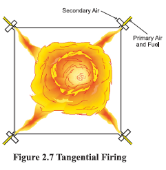
burner nozzles. Secondary and tertiary air may also be added. Combustion takes place at temperatures from 1300-1700°C, depending largely on coal grade. Particle residence time in the boiler is typically 2 to 5 seconds,and the particles must be small enough for complete combustion to have taken place during this time. This system has many advantages such as ability to fire varying quality of coal, quick responses to changes in load, use of high pre-heat air temperatures etc. One of the most popular systems for firing pulverized coal is the tangential firing using four burners corner to corner to create a fireball at the center of the furnace(see Figure 2.7).
FBC Boiler
When an evenly distributed air or gas is passed upward through a finely divided bed of solid particles such as sand supported ona fine mesh, the particles are undisturbed at low velocity. As air velocity is gradually increased, a stage is reached when the individual particles are suspended in the air stream. Further, increase in velocity gives rise to bubble formation, vigorous turbulence and rapid mixing and the bed is said to be fluidized (Figure 2.8).

If the sand in a fluidized state is heated to the ignition temperature of the coal and the coal is injected continuously in to the bed, the coal will burn rapidly, and the bed attains a uniform temperature due to effective mixing. Proper air distribution is vital for maintaining uniform fluidisation across the bed.). Ash is disposed by dry and wet ash disposal systems.
Fluidised bed combustion has significant advantages over conventional firing systems and offers
multiple benefits namely fuel flexibility, reduced emission of noxious pollutants such as SOx and NOx,
compact boiler design and higher combustion efficiency. More details about FBC boilers are given in
Chapter 6 on Fluidized Bed Boiler.
Super Critical Boiler
In the temperature entropy diagram of steam, a point is reached where the boiling water and dry
saturated steam lines converge and at that point, the latent heat is zero. The critical point corresponds
to a pressure of 221.2 bar absolute and a temperature of 374.18 °C.
If water is heated beyond the above condition, steam parameters are referred to as super critical. A
boiler producing steam above the critical pressure is called the supercritical boiler. While sub-critical
boiler has three distinct sections - economiser, evaporator and superheater the supercritical boiler has
only an economiser and superheater. The advantages of super critical boilers are
1.Higher heat transfer rate
2.More flexible in accepting load variation
3.Grater ease of operation
4.High thermal efficiency (40-42% of power generating stations)
5.The absence of two-phase mixer minimise the problems of erosion and corrosion
6.Steadier pressure level
Typical improvements in station heat rate with increasing pressures and temperatures are given in
Table 2.1.

The super critical boilers call for special materials to be used for constituent heat transfer surfaces like
drum, water walls, economizer and re-heaters, in order to withstand the elevated pressure & temperature conditions.
Performance Evaluation of Boilers
The performance parameters of a boiler like evaporation ratio and efficiency deteriorate with time due
to poor combustion, heat transfer surface fouling and poor operation and maintenance. Even for a new
boiler, reasons such as deteriorating fuel quality, water quality etc, can result in poor boiler performance.
Evaporation ratio trending and Boiler efficiency tests help to find out the deviation of boiler efficiency
from the rated values and target problem areas for corrective action.
Boiler Evaporation Ratio
Boiler Evaporation ratio, also known as Steam to fuel ratio, is a common and simple indicator for
boiler performance trending.
Evaporation ratio monitoring is best suited for any boiler when its own performance is compared on
day to day basis as a performance indicator; given that enthalpy gain in steam and fuel calorific value
remain constant. A drop in evaporation ratio indicates a drop in Boiler efficiency.
Typical values of Evaporation ratio for different type of fuels are as follows:
Biomass fired boilers : 2.0 to 3.0
Coal fired boilers : 4.0 to 5.5
Oil fired boilers : 13.5 to 14.5
Gas fired boilers : 11.0 to 13.0
Boiler Efficiency
Thermal efficiency of a boiler is defined as the percentage of heat input that is effectively utilized to
generate steam. There are two methods of assessing boiler efficiency.
a) Direct method: Where the energy gain of the working fluid (water and steam) is compared with
the energy content of the boiler fuel.
b) Indirect or Loss method: Where the efficiency is the difference between the losses and the
energy input

Direct Method
This is also known as ‘input-output method’ due to the fact that it needs only the useful output (steam)
and the heat input (i.e. fuel) for evaluating the efficiency. This efficiency can be evaluated using the
formula

Parameters to be monitored for the calculation of boiler efficiency by direct method are :
1.Quantity of steam generated per hour (Q) in kg/hr.
2.Quantity of fuel used per hour (q) in kg/hr.
3.The working pressure (in kg/cm?(g)) and superheat temperature (°C), if any
4.The temperature of feed water (°C)
5.Type of fuel and gross calorific value of the fuel (GCV) in kcal/kg of fuel
Where,
h, — Enthalpy of saturated steam in kcal/kg of steam
h, - Enthalpy of feed water in kcal/kg of water
The fuel calorific value may be gross or net and accordingly, the efficiency reported is referred to as
efficiency on GCV or NCV basis.
Example
Find out the efficiency and evaporation ratio of the boiler by direct method with the data given below:
Type of boiler : Coal fired
Quantity of steam (dry) generated : 8 TPH
Steam pressure / temp : 10 kg/cm2(g)/ 180 °C
Quantity of coal consumed : 1.8 TPH
Feed water temperature : 85°C
GCV of coal : 3200 kcal/kg
Enthalpy of saturated steam at 10 kg/cm2 Pressure : 665 kcal/kg
Enthalpy of feed water : 85 kcal/kg

It should be noted that boiler may not generate 100% saturated dry steam, and there may be some
amount of wetness in the steam.
Advantages of direct method:
1.Plant people can evaluate the efficiency of boilers quickly
2.Requires few parameters for computation
3.Needs few instruments for monitoring
The constraints with the direct efficiency method:
1.Accuracy of steam/feed water flow measurement and fuel measurement are prone to errors
2.Steam quality assessment in case of saturated steam conditions is prone to error as prevalence
of wet steam is common in many boilers.
3.The reported efficiency gives only values with respect to design but does not indicate any
improvement opportunities
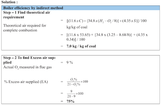
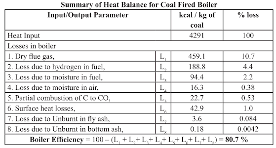
The Indirect or Heat Loss Method
Indirect method is also called as heat loss method. The efficiency is arrived at, by subtracting the heat
loss fractions from 100. The standards do not include blow down loss in the efficiency determination
process. A detailed procedure for calculating boiler efficiency by indirect method is given below along
with example.


Boiler Water Treatment
Producing quality steam on demand depends on properly managed water treatment to control steam
purity, deposits and corrosion. A boiler is the sump of the boiler system. It ultimately receives all of
the pre-boiler contaminants. Boiler performance, efficiency, and service life are direct products of
selecting and controlling feed water used in the boiler.
When feed water enters the boiler, the elevated temperatures and pressures cause the components of
water to behave differently. Most of the components in the feed water are soluble. However, under
heat and pressure most of the soluble components come out of solution as particulate solids, sometimes
in crystallized forms and other times as amorphous particles. When solubility of a specific component
in water is exceeded, scale or deposits develop. The boiler water must be sufficiently free of deposit
forming solids to allow rapid and efficient heat transfer and it must not be corrosive to the boiler metal.
Deposit Control
Deposits in boilers may result from hardness contamination of feed water and corrosion products from
the condensate and feed water system. Hardness contamination of the feed water may arise due to
deficient softener system.
Deposits and corrosion result in efficiency losses and may result in boiler tube failures and inability
to produce steam. Deposits act as insulators and slow heat transfer. Large amounts of deposits throughout
the boiler could reduce the heat transfer enough to reduce the boiler efficiency significantly. Different
type of deposits affects the boiler efficiency differently. Thus it may be useful to analyse the deposits
for its characteristics. The insulating effect of deposits causes the boiler metal temperature to rise and
may lead to tube-failure by overheating.
Impurities causing deposits
The most important chemicals contained in water that influences the formation of deposits in the
boilers are the salts of calcium and magnesium, which are known as hardness salts. Calcium and magnesium bicarbonate dissolve in water to form an alkaline solution and these salts are
known as alkaline hardness. They decompose upon heating, releasing carbon dioxide and forming a
soft sludge, which settles out.
These are called temporary hardness-hardness that can be removed by
boiling.
Calcium and magnesium sulphates, chlorides and nitrates, etc. when dissolved in water are chemically
neutral and are known as non-alkaline hardness. These are called permanent hardness and form hard
scales on boiler surfaces, which are difficult to remove. Non-alkalinity hardness chemicals fall out the
solution due to reduction in solubility as the temperature rises, by concentration due to evaporation
which takes place within the boiler, or by chemical change to a less soluble compound.
Silica
The presence of silica in boiler water can rise to formation of hard silicate scales. It can also associate
with calcium and magnesium salts, forming calctum and magnesium silicates of very low thermal
conductivity. Silica can give rise to deposits on steam turbine blades, after been carried over either in
droplets of water in steam, or in volatile form in steam at higher pressures.
Two major types of boiler water treatment are: Internal water treatment and External water treatment.
Internal Water Treatment
Internal treatment is carried out by adding chemicals to boiler to prevent the formation of scale by
converting the scale-forming compounds to free-flowing sludges, which can be removed by blow
down. This method is limited to boilers, where feed water is low in hardness salts, to low pressureshigh TDS content in boiler water is tolerated, and when only small quantity of water is required to be
treated. If these conditions are not applied, then high rates of blow down are required to dispose off
the sludge.
They become uneconomical from heat and water loss consideration.
Different waters require different chemicals. Sodium carbonate, sodium aluminate, sodium phosphate,
sodium sulphite and compounds of vegetable or inorganic origin are all used for this purpose. Proprietary
chemicals are available to suit various water conditions. The specialist must be consulted to determine
the most suitable chemicals to use in each case. Internal treatment alone is not recommended.
External Water Treatment
External treatment is used to remove suspended solids, dissolved solids (particularly the calcium and
magnesium ions which are major causes of scale formation) and dissolved gases (oxygen and carbon
dioxide).
The external treatment processes available are: ion exchange; demineralization; reverse osmosis and
de-aeration. Before any of these are used, it is necessary to remove suspended solids and colour from
the raw water, because these may foul the resins used in the subsequent treatment sections.
Methods of pre-treatment include simple sedimentation in settling tanks or settling in clarifiers with
aid of coagulants and flocculants. Pressure sand filters, with spray aeration to remove carbon dioxide
and iron, may be used to remove metal salts from bore well water.
The first stage of treatment is to remove hardness salt and possibly non-hardness salts. Removal of
only hardness salts is called softening, while total removal of salts from solution is called
demineralization.
The processes are:
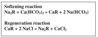
Ion-exchange process (Softener Plant)
In ion-exchange process, the hardness is removed as the water passes through bed of natural zeolite or synthetic resin and without the formation of any
precipitate. The simplest type is ‘base exchange’ in which calcium and magnesium ions are exchanged for sodium ions. After saturation regeneration is done
with sodium chloride. The sodium salts being soluble,
do not form scales in boilers. Since base exchanger only replaces the calcium and magnesium with
sodium, it does not reduce the TDS content, and blowdown quantity. It also does not reduce the
alkalinity.
Demineralization is the complete removal of all salts. This is achieved by using a “cation” resin, which
exchanges the cations in the raw water with hydrogen ions, producing hydrochloric, sulphuric and
carbonic acid. Carbonic acid is removed in degassing tower in which air is blown through the acid
water. Following this, the water passes through an “anion” resin which exchanges anions with the
mineral acid (e.g. sulphuric acid) and forms water. Regeneration of cations and anions is necessary at
intervals using, typically, mineral acid and caustic soda respectively. The complete removal of silica
can be achieved by correct choice of anion resin.
Ion exchange processes can be used for almost total demineralization if required, as is the case in large
electric power plant boilers
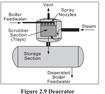
De-aeration
In de-aeration (Figure 2.9), dissolved gases, such as oxygen and carbon dioxide, are expelled by preheating the feed water before it enters the boiler. All natural waters contain dissolved gases in solution. Certain gases, such as carbon dioxide and oxygen, greatly increase
corrosion. When heated in boiler systems, carbon dioxide (CO,) and oxygen (O,) are released as gases and combine with water (H,O) to form carbonic acid, (H,CO,).
Removal of oxygen, carbon dioxide and other non-condensable gases from boiler feed water is vital
to boiler equipment longevity as well as safety of operation. Carbonic acid corrodes metal reducing
the life of equipment and piping. It also dissolves iron (Fe) which when returned to the boiler precipitates
and causes scaling on the boiler and tubes. This scale not only contributes to reducing the life of the
equipment but also increases the amount of energy needed to achieve heat transfer.
De-aeration can be done by mechanical de-aeration, by chemical de-aeration or by both together.
Mechanical de-aeration
Mechanical de-aeration for the removal of these dissolved gases is typically utilized prior to the addition
of chemical oxygen scavengers. Mechanical de-aeration is based on Charles’ and Henry’s laws of
physics. Simplified, these laws state that removal of oxygen and carbon dioxide can be accomplished
by heating the boiler feed water, which reduces the concentration of oxygen and carbon dioxide in the
atmosphere surrounding the feed water. Mechanical de-aeration can be the most economical. They
operate at the boiling point of water at the pressure in the de-aerator. They can be of vacuum or pressure
type.
The vacuum type of de-aerator operates below atmospheric pressure, at about 82 C, can reduce the
oxygen content in water to less than 0.02 mg/litre. Vacuum pumps or steam ejectors are required to
maintain the vacuum.
The pressure-type de-aerators operates by allowing steam into the feed water through a pressure control
valve to maintain the desired operating pressure, and hence temperature at a minimum of 105°C. The
steam raises the water temperature causing the release of O, and CO, gases that are then vented from
the system. This type can reduce the oxygen content to 0.005 mg/litre.
Where excess low-pressure steam is available, the operating pressure can be selected to make use of
this steam and hence improve fuel economy. In boiler systems, steam is preferred for de-aeration
because:
° Steam is essentially free from O, and CO,
° Steam is readily available
° Steam adds the heat required to complete the reaction.
Chemical de-aeration
While the most efficient mechanical deaerators reduce oxygen to very low levels (0.005 mg/litre),
even trace amounts of oxygen may cause corrosion damage to a system. Consequently, good operating
practice requires removal of that trace oxygen with a chemical oxygen scavenger such as sodium sulfite
or hydrazine. Sodium sulphite reacts with oxygen to form sodium sulphate, which increases the TDS
in the boiler water and hence increases the blow down requirements and make-up water quality.
Hydrazine reacts with oxygen to form nitrogen and water. It is invariably used in high pressures boilers
when low boiler water solids are necessary, as it does not increase the TDS of the boiler water.
Reverse Osmosis
When solutions of differing concentrations are separated by a semi-permeable membrane, water from
less concentrated solution passes through the membrane to dilute the liquid of high concentration,
which is called osmosis. If the solution of high concentration is pressurized, the process is reversed
and the water from the solution of high concentration flows to the weaker solution. This is known as
reverse osmosis.
The quality of water produced depends upon the concentration of the solution on the high-pressure
side and pressure differential across the membrane. This process is suitable for waters with very high
TDS, such as sea water.


Recommended boiler and feed water quality
The impurities found in boiler water depend on the untreated feed water quality, the treatment process
used and the boiler operating procedures. As a general rule, the higher the boiler operating pressure,
the greater will be the sensitivity to impurities. Recommended feed water and boiler water limits are
shown in Table 2.2 and Table 2.3.


Boiler Blow Down
When water is boiled and steam is generated, any dissolved solids contained in the water remain in
the boiler. If more solids are put in with the feed water, they will concentrate and may eventually reach
a level where their solubility in the water is exceeded and they deposit from the solution. Above a
certain level of concentration, these solids encourage foaming and cause carryover of water into the
steam. The deposits also lead to scale formation inside the boiler, resulting in localized overheating
and finally causing boiler tube failure.
It is, therefore, necessary to control the level of concentration of the solids and this is achieved by the
process of ‘blowing down’, where a certain volume of water is blown off and is automatically replaced
by feed water - thus maintaining the optimum level of total dissolved solids (TDS) in the boiler water.
Blow down is necessary to protect the surfaces of the heat exchanger in the boiler. However, blow
down can be a significant source of heat loss, if improperly carried out. The maximum amount of total
dissolved solids (TDS) concentration permissible in various types of boilers is given in Table 2.4.

Note: Refer guidelines specified by manufacturer for more details
*parts per million
Conductivity as Indicator of Boiler Water Quality
Since it is tedious and time consuming to measure total dissolved solids (TDS) in boiler water system,
conductivity measurement is used for monitoring the overall TDS present in the boiler. A rise in
conductivity indicates a rise in the “contamination” of the boiler water.
Conventional methods for blowing down the boiler depend on two kinds of blow down - intermittent
and continuous
Intermittent Blow Down
The intermittent blown down is given by manually operating a valve fitted to discharge pipe at the
lowest point of boiler shell to reduce parameters (TDS or conductivity, pH, Silica and Phosphates
concentration) within prescribed limits so that steam quality is not likely to be affected. In intermittent
blow down, a large diameter line is opened for a short period of time, the time being based on a thumb
rule such as “once in a shift for 2 minutes”.
Intermittent blow down requires large short-term increases in the amount of feed water put into the
boiler, and hence may necessitate larger feed water pumps than if continuous blow down is used. Also,
TDS level will be varying, thereby causing fluctuations of the water level in the boiler due to changes in steam bubble size and distribution which accompany changes in concentration of solids. Also
substantial amount of heat energy is lost with intermittent blow down.

Blow down calculations
The quantity of blow down required to control boiler water solids concentration is calculated by using
the following formula:
If maximum permissible limit of TDS as in a package boiler is 3000 ppm, percentage make up water
is 10% and TDS in feed water is 300 ppm, then the percentage blow down is given as:

If boiler evaporation rate is 3000 kg/hr then required blow down rate is:
Benefits of Blow Down
Good boiler blow down control can significantly reduce treatment and operational costs that include:
¢ Lower pre-treatment costs
¢ Less make-up water consumption
¢ Reduced maintenance downtime
¢ Increased boiler life
¢ Lower consumption of treatment chemicals
Improving Boiler Availability
i) Reducing Boiler Tube Leakage
Tube failures in boilers lead to reduction in availability and call for continuous efforts to minimize the
tube leakages.
Tube failures can be attributed to design, manufacturing, operational, maintenance and ageing related
aspects. The tube failures mechanisms can be classified as Mechanical, chemical, metallurgical & in
adequate quality compliance.
Mechanical causes
Mechanical damage of tubes takes place due to fly ash erosion, steam impingement from soot blowers,
falling clinker and fuel particles. The Mechanical damage increases the stress level leading to tube
failure.
Chemical causes
Water side and fire side corrosion failure of tubes occurs due to phenomenon like caustic gouging,
hydrogen embrittlement, pitting, and stress corrosion cracking while fire side corrosion is often due
to high as well as low temperature effects
Metallurgical causes
In high temp components like superheaters, reheaters creep damage occurs due to overheating wherein
the tube material loses its strength and failure occurs by stress rupture. Weld joint failures by cracking
and fatigue failures by vibration, thermal and corrosion phenomenon are other reasons for metallurgical
related tube failures. '
Quality assurance gaps
Tube failures are also known to occur due to inadequate quality assurance procedures during design/
manufacturing of boiler tubes. Due care during material procurement, adoption of healthy fabrication
practices, good operation and maintenance practices in tube manufacturing would help to minimize
tube leakages and achieve high availability.
ii) Soot Blowing and Soot Deposit Reduction
One of the important by-products of the combustion of solid fuels is ash. During combustion, some
of the mineral constituents and compounds can be in a molten or plastic state. The ash constituents
can then deposit on the heat-absorbing surfaces causing slagging and fouling. If ash reaches the heatabsorbing surfaces at a temperature near its softening temperature, the resulting deposits are likely to
be porous and can be removed by soot blowing.
Slagging is the deposition of molten, partially fused
deposits on the furnace walls and the radiant superheaters exposed to radiant heat. Fouling is the
deposition of more loosely bonded deposits on the heat-absorbing surfaces in the convective path.
Soot blowers using steam are generally used for removing ash deposits on fouled tube surfaces, while
water lances or water canons using thermal shock by room-temperature water may be needed to clean
the slagged tube surfaces.
A Soot blower is a system for removing the soot that is deposited on the furnace tubes of a boiler
during combustion. Various types of soot blowers such as Wall Blowers, Long Retractable Blowers
and Air Heater Blowers are used for the cleaning. Steam is normally used as a medium for blowing
away the soot.
The soot which sticks to the heating surfaces insulates them from the heat, reducing their efficiency.
Soot must be blown off to maximize heat transfer in the boiler. Elevated stack temperatures may
indicate excessive soot build-up. High exit gas temperatures at normal excess air indicate poor heat
transfer performance.
Stack temperature should be checked and recorded regularly as an indicator of soot deposits. When
the flue gas temperature raises by about 20 °C above the normal temperature for a newly cleaned boiler,
soot deposits are the main concern. It is estimated that 3 mm of soot can cause an increase in fuel
consumption by 2.5% due to increased flue gas temperatures.
iii) Preservation of Boiler
The internal surfaces of the boiler are prone to corrosion by leftover water after operation or by
atmospheric oxygen when they are out of service. Hence boiler preservation is required to protect the
internal surfaces from corrosion. There are two methods of preservation a) wet method and b) dry
method.
Boilers which are kept ready for standby service and may be required for sudden demands of operations
are preserved by wet method. Dry method is recommended for boilers which are scheduled to be kept
out of service for a long period and are not expected to be put into operation at short notice.
a) Wet method
In the wet method the boiler is filled to the normal level with water at a pH of 10.5 to 11. Hydrazine
to the extent of 200 ppm is to be dosed with the water. The unit is to be steamed in service to ensure
uniform concentration of boiler water throughout the unit and to eliminate dissolved oxygen from
water. Sodium sulphite (Na,SO,), which acts as a de-oxygenerator, can also be used as an alternative
to hydrazine and the sulphite concentration has to be maintained at 300-400 ppm.
Analysis of boiler water should be carried out frequently. If the hydrazine concentration in water
happens to drop below 50 ppm, the water in the drum should be lowered to the normal operating level
and an appropriate quantity of chemicals should be dosed to bring back 200 the concentration of
hydrazine or sodium sulphite. The boiler should be steamed to circulate chemicals to uniform
concentration.
b) Dry method
This is mainly done to preserve the internal surfaces of the boiler. The boiler is filled with deaerated
water and fired to raise the pressure to 7 kg/cm’. The firing is now stopped and the pressure is allowed
to drop to 2-3 kg/cm”, the water is then drained out of the boiler. All the drain pockets and manhole
doors are kept open. Hot air is blown through the blowers to completely dry the internal surfaces. After
thorough drying trays containing silica gel or activated alumina (0.25 kg/m? of heating surface) should
be placed inside the drum. Alternatively, anhydrous calcium chloride or un-slaked lime (0.098 kg/m?
of heating surface) may be used as a desiccant. The pressure parts are then closed air tight to avoid
any moisture/air leaking in. the inspection should be carried out once in a month and the desiccant
trays replenished accordingly.
Another method of dry preservation is to keep the boiler under positive pressure by using pure nitrogen.
iv) Cold Start up and Shutdown Procedures:
a) Cold start up procedure
Starting up of boiler should not be speeded up, and it normally takes about four hours to complete.
Strict adherence to the manufacturer’s recommended procedures will make the boiler operation more
efficient and safer. A typical cold start procedure is given below.
1. Check that the boiler is properly closed up (especially after repairs).
2.Check physically that all appropriate valves are shut or open for safe starting of the boiler.
3.Boiler is to be filled to slightly below normal level.
Boiler treatment chemicals may now be added to the boiler water.
4.Check and clear the furnace of any flammable materials.
Ensure that the boiler uptakes passage is clear.
5.Pre-purging of furnace for a specified amount of time is necessary to clear the gas-side of
flammable gases to avoid a staring explosion.
6.Onacold boiler, firing-up must not be speeded up too much in order not to overstrain the boiler material unnecessarily by quick, uneven temperature raises.
Keep the boiler vents open until a heavy steam jet is flowing out (until a boiler pressure of about 1 bar
is reached).
b) Boiler shut down procedures
During normal operations, the boiler water chemistry is carefully controlled so that the dissolved/
suspended material is conditioned to prevent hard deposits on boiler metal. These dissolved/suspended solids are maintained in suspension by water circulation and the action of the treatment chemicals.
When a boiler is shut down or drained, this material (sludge) may settle and bake on tube surfaces; it
may become so adherent that mechanical (turbining) chemical cleaning may be required. A typical
shutdown procedure to avoid such problem, is given below.
Three to five days before a scheduled shut down, increase the blow down by 50%.
o If possible, increase the alkalinity to at least 500 ppm without causing foaming or carryover.
o Due to the increased blow down rate, the feed rate of the scale inhibitor and oxygen scavenger
must be increased so as to maintain the normal boiler water residuals.
o Increase the sludge conditioner level in the boiler water by 50 to 100%.
During the last twenty-four hours before shut down, decrease the continuous blow down and increase
the manual blow down.
o Frequent short bottom blows are better than fewer longer blows.
o Generally it is sufficient to hold each mud drum blow down valve open for about 5-10 seconds
every one to two hours.
o Once the load is dropped from the boiler, include the header blow downs as part of the manual
blow down procedure.
o When the load is dropped from the boiler, continue bottom blow downs until boiler is cool and
safe to work on.
o As soon as possible after the boiler is opened, wash down the boiler watersides, preferably
with soft water.
Thermic Fluid Heaters
Water/steam is used as heat carrier in many heating applications. However, at high temperatures, steam
requires a corresponding high operating pressure. Industrial heating systems, a high temperature level
is often a great advantage, and establishing this with steam can be very cumbersome and expensive
in some cases.
In thermic fluid heaters, a special type of oil-synthetic / mineral -is used as heat carrier. This fluid can
be heated up to 300°C at atmospheric pressure. In comparison steam would require a pressure of 85
bars to obtain this temperature.
There are several advantages in using thermic fluids compared to steam systems. The most obvious
advantages are as follows.
o High temperature operation at atmospheric pressure
o Optional temperature level set points
o No supply of treatment of heat water and hence no heat loss due to condensate flash
steam
o Norisk of corrosion
o Easy to operate
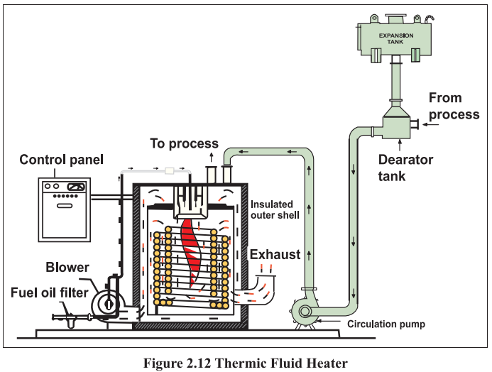
The heaters are made with coils of seamless tubes. The thermal fluid is heated during the flow through the tubes (Refer Figure 2.12). The heat is transferred to the fluid as radiant heat in the combustion
chamber, where the inner cylindrical tube coil and a flat tube coil form the chamber wall and the bottom
respectively. The hot thermic fluid is circulated to various process equipments such as dryers, heaters,
deodouriser etc. where it gives up the heat. The return oil at a temperature 10 to 20 °C less comes back
to the thermic fluid heater to get heated up again. The circulation is carried out by a thermic fluid
circulation pump.
The thermic fluid heater operates between two temperature ranges. Once the upper limit is reached
the burner is switched OFF or goes into the low fire mode. In the case of solid fuel fired system the
ID fan switches OFF on reaching the upper limit. When the temperature reaches the lower limit due
to heat transfer in the process, the burners come ON again and in case of solid fuels, the ID fan comes
ON again.
Since the thermic fluid heaters operate at a high temperature (250 — 300 °C), the leaving exhaust gas
temperatures are more than the fluid temperature. Hence, the heat loss through the flue gas is a major
component of fuel losses. This offers potential for heat recovery if there is a suitable application. The
capacity of the thermic fluid heater is specified in terms of Lakh kilo Calories per hour or Million kilo
Calories per hour.
Energy Conservation Opportunities
The various energy efficiency opportunities in boiler system can be related to combustion, heat transfer,
avoidable losses, high auxiliary power consumption, water quality and blow down. Examining the
following factors can indicate if a boiler is being run to maximize its efficiency:
1. Stack Temperature
The stack temperature should be as low as possible. However, it should not be so low that water vapor
in the exhaust condenses on the stack walls. This is important in fuels containing significant sulphur
as low temperature can lead to sulphur dew point corrosion. Stack temperatures greater than 200 °C
indicates potential for recovery of waste heat. It also indicate the scaling of heat transfer/recovery
equipment and hence the urgency of taking an early shut down for water / flue side cleaning.
2. Feed Water Preheating using Economiser
Typically, the flue gases leaving a modern 3-pass shell boiler are at temperatures of 200 to 300 °C.
Thus, there is a potential to recover heat from these gases. The flue gas exit temperature from a boiler
is usually maintained at a minimum of 200°C, so that the sulphur oxides in the flue gas do not condense
and cause corrosion in heat transfer surfaces. When a clean fuel such as natural gas, LPG or gas oil
is used, the economy of heat recovery must be worked out, as the flue gas temperature may be well
below 200 °C.
The potential for energy saving depends on the type of boiler installed and the fuel used. Fora
typically older model shell boiler, with a flue gas exit temperature of 260 °C, an economizer could be
used to reduce it to 200 °C, increasing the feed water temperature by 15 °C. Increase in overall thermal
efficiency would be in the order of 3%. For a modern 3-pass shell boiler firing natural gas with a flue
gas exit temperature of 140 °C a condensing economizer would reduce the exit temperature to 65 °C
increasing thermal efficiency by 5%.
3. Combustion Air Preheat
Combustion air preheating is an alternative to feedwater heating. In order to improve thermal efficiency
by 1%, the combustion air temperature must be raised by 20°C. Most gas and oil burners used in a
boiler plant are not designed for high air preheat temperatures.
Modern burners can withstand much higher combustion air preheat, so it is possible to consider such
units as heat exchangers in the exit flue as an alternative to an economizer, when either space or a high
feed water return temperature make it viable.
4. Incomplete Combustion
Incomplete combustion can arise from a shortage of air or surplus of fuel or poor distribution of fuel.
It is usually obvious from the colour or smoke, and must be corrected immediately.
In the case of oil and gas fired systems, CO or smoke (for oil fired systems only) with normal or high
excess air indicates burner system problems. A more frequent cause of incomplete combustion is the
poor mixing of fuel and air at the burner. Poor oil fires can result from improper viscosity, worn tips,
carbonization on tips and deterioration of diffusers or spinner plates.
With coal firing, unburned carbon can comprise a big loss. It occurs as grit carry-over or carbon-inash and may amount to more than 2% of the heat supplied to the boiler. Non uniform fuel size could
be one of the reasons for incomplete combustion. In chain grate stokers, large lumps will not burn out
completely, while small pieces and fines may block the air passage, thus causing poor air distribution.
In sprinkler stokers, stoker grate condition, fuel distributors, wind box air regulation and over-fire
systems can affect carbon loss. Increase in the fines in pulverized coal also increases carbon loss.
5. Excess Air Control
The Table 2.5 gives the theoretical amount of air required for combustion of various types of fuel. Excess
air is required in all practical cases to ensure complete combustion, to allow for the normal variations in
combustion and to ensure satisfactory stack conditions for some fuels. The optimum excess air level for
maximum boiler efficiency occurs when the sum of the losses due to incomplete combustion and loss
due to heat in flue gases is minimum. This level varies with furnace design, type of burner, fuel and
process variables. It can be determined by conducting tests with different air fuel ratios.

Typical values of excess air supplied for various fuels are given in Table — 2.6

Controlling excess air to an optimum level always results in reduction in flue gas losses; for every 1%
reduction in excess air there is approximately 0.6% rise in efficiency.
Various methods are available to control the excess air:
¢ Portable oxygen analysers and draft gauges can be used to make periodic readings to guide the
operator to manually adjust the flow of air for optimum operation. Excess air reduction up to
20% is feasible.
¢ The most common method is the continuous oxygen analyzer with a local readout mounted draft
gauge, by which the operator can adjust air flow. A further reduction of 10-15% can be achieved
over the previous system.
¢ The same continuous oxygen analyzer can have a remote controlled pneumatic damper positioner,
by which the readouts are available in a control room. This enables an operator to remotely
control a number of firing systems simultaneously.
The most sophisticated system is the automatic stack damper control, whose cost is really justified
only for large systems.
6. Radiation and Convection Heat Loss
The external surfaces of a shell boiler are hotter than the surroundings. The surfaces thus lose heat to
the surroundings depending on the surface area and the difference in temperature between the surface
and the surroundings.
The heat loss from the boiler shell is normally a fixed energy loss, irrespective of the boiler output.
With modern boiler designs, this may represent only 1.5% on the gross calorific value at full rating,
but will increase to around 6%, if the boiler operates at only 25 percent output.
Repairing or augmenting insulation can reduce heat loss through boiler walls and piping.
7. Automatic Blowdown Control
Uncontrolled continuous blowdown is very wasteful. Automatic blowdown controls can be installed
that sense and respond to boiler water conductivity and pH. A 10% blow down in a 15 kg/cm2 boiler
results in 3% efficiency loss.
8. Reduction of Boiler Steam Pressure
This is an effective means of reducing fuel consumption, if permissible, by as much as | to 2%. Lower
steam pressure gives a lower saturated steam temperature and without stack heat recovery, a similar
reduction in the temperature of the flue gas temperature results.
Steam is generated at pressures normally dictated by the highest pressure / temperature requirements
for a particular process. In some cases, the process does not operate all the time, and there are periods
when the boiler pressure could be reduced. The energy manager should consider pressure reduction carefully, before recommending it. Adverse effects, such as an increase in water carryover from the
boiler owing to pressure reduction, may negate any potential saving. Pressure should be reduced in
stages, and no more than a 20 percent reduction should be considered.
9. Variable Speed Control for Fans, Blowers and Pumps
Variable speed control is an important means of achieving energy savings. Generally, combustion air
control is effected by throttling dampers fitted at forced and induced draft fans. Though dampers are
simple means of control, they lack accuracy, giving poor control characteristics at the top and bottom
of the operating range. In general, if the load characteristic of the boiler is variable, the possibility of
replacing the dampers by a VSD should be evaluated.
10. Effect of Boiler Loading on Efficiency
The maximum efficiency of the boiler does not occur at full load, but at about two-thirds of the full
load. If the load on the boiler decreases further, efficiency also tends to decrease. At zero output, the
efficiency of the boiler is zero, and any fuel fired is used only to supply the losses. The factors affecting
boiler efficiency are:
o As the load falls, so does the value of the mass flow rate of the flue gases through the tubes. This
reduction in flow rate for the same heat transfer area, reduced the exit flue gas temperatures by
a small extent, reducing the sensible heat loss.
o Below half load, most combustion appliances need more excess air to burn the fuel completely.
This increases the sensible heat loss.
In general, efficiency of the boiler reduces significantly below 25% of the rated load and as far as
possible; operation of boilers below this level should be avoided.
11. Proper Boiler Scheduling
Since, the optimum efficiency of boilers occurs at 65-85% of full load, it is usually more efficient, on
the whole, to operate a fewer number of boilers at higher loads, than to operate a large number at low
loads.
12. Boiler Replacement
The potential savings from replacing a boiler depend on the anticipated change in overall efficiency.
A change in a boiler can be financially attractive if the existing boiler is :
¢ Old and inefficient
¢ Not capable of firing cheaper substitution fuel
¢ Over or under-sized for present requirements
¢ Not designed for ideal loading conditions
The feasibility study should examine all implications of long-term fuel availability and company growth plans. All financial and engineering factors should be considered. Since boiler plants traditionally have a useful life of well over 25 years, replacement must be carefully studied.
Solved Example:
An oil fired boiler is generating 30 T/hr Steam and operates for 8000 hrs/year. The TDS in boiler feed
water was reduced from 500 ppm to 200 ppm. The maximum permissible limit of TDS in the boiler
is 3000 ppm and make up water is 10%.
Temperature of the blow down water is 170°C and boiler feed water temperature is 40°C. GCV of fuel
is 10000 kcal/kg and efficiency of the boiler is 80%.
Calculate the savings in fuel oil per annum due to reduction in the blow down.

---------------------
Chapter 3
Comments
Post a Comment