Energy efficiency in Thermal utilities
(Chapter 1: Fuels and Combustion)
Introduction to Fuels
The various types of fuels like liquid, solid and gaseous fuels are available for firing in boilers, furnaces
and other combustion equipments. The selection of right type of fuel depends on various factors such
as availability, storage, handling, pollution and landed cost of fuel.
The knowledge of the fuel properties helps in selecting the right fuel for the right purpose and efficient
use of the fuel. The following characteristics, determined by laboratory tests, are generally used for
assessing the nature and quality of fuels.
Properties of Liquid Fuels
Liquid fuels like furnace oil and LSHS are predominantly used in industrial application. The various
properties of liquid fuels are given below.
Density
This is defined as the ratio of the mass of the fuel to the volume of the fuel at a reference temperature
of 15°C. Density is measured by an instrument called hydrometer. The knowledge of density is useful
for quantity calculations and assessing ignition quality. The unit of density is kg/m .
Specific gravity
This is defined as the ratio of the weight of a given volume of oil to the weight of the same volume of
water at a given temperature. The density of fuel, relative to water, is called specific gravity. The
specific gravity of water is defined as 1. Since specific gravity is a ratio, it has no units. The measurement of specific gravity is generally made by a hydrometer.
Specific gravity is used in calculations involving weights and volumes. The specific gravity of various
fuel oils are given in Table 1.1

Viscosity
The viscosity of a fluid is a measure of its internal resistance to flow. Viscosity depends on temperature
and decreases as the temperature increases. Any numerical value for viscosity has no meaning
unless the temperature is also specified. Viscosity is measured in Stokes / Centistokes. Sometimes viscosity
is also quoted in Engler, Saybolt or Redwood. Each type of oil has its own temperature - viscosity
relationship. The measurement of viscosity is made with an instrument called Viscometer.
Viscosity is the most important characteristic in the storage and use of fuel oil. It influences the
degree of pre-heat required for handling, storage and satisfactory atomization. If the oil is too viscous,
it may become difficult to pump, hard to light the burner, and tough to operate. Poor atomization
may result in the formation of carbon deposits on the burner tips or on the walls. Therefore preheating
is necessary for proper atomization.
The calorific value is the measurement of heat or energy produced, and is measured either as gross
calorific value or net calorific value. The difference being the latent heat of condensation of the
water vapour produced during the combustion process. Gross calorific value (GCV) assumes all
vapour produced during the combustion process is fully condensed.
Net calorific value (NCV)
assumes the water leaves with the combustion products without fully being condensed. Fuels should
be compared based on the net calorific value.
The calorific value of coal varies considerably depending on the ash, moisture content and the type of
coal while calorific value of fuel oil is much more consistent. The typical Gross Calorific Values of
some of the commonly used liquid fuels are given below:

The following conversion formula shows the difference between GCV and NCV.
GCV = NCV + 584 ((9H,% + M%)/100)
Where,
GCV= Gross calorific value of fuel, kcal/kg
NCV = Net calorific value of fuel, kcal/kg
H,%= Hydrogen % by weight present in the fuel
M% = Moisture % by weight present in the fuel
584 = Latent heat corresponding to partial pressure of water vapour, kcal/kg
Sulphur
The amount of sulphur in the fuel depends mainly on the source of the crude oil and to a lesser
extent on the refining process. The normal sulfur content for the residual fuel oil (furnace oil) is in the
order of 2-4 %.
Typical figures are:

The main disadvantage of sulphur is the risk of corrosion by sulphuric acid formed during and after
combustion, and condensing in cool parts of the chimney or stack, air pre heater and economiser.
Ash Content
The ash value is related to the inorganic material in the fuel oil. The ash levels of distillate fuels are
negligible. Residual fuels have more of the ash-forming constituents. These salts may be compounds
of sodium, vanadium, calctum, magnesium, silicon, iron, aluminum, nickel, etc.
Typically, the ash value is in the range 0.03-0.07 %. Excessive ash in liquid fuels can cause fouling
deposits in the combustion equipment. Ash has erosive effect on the burner tips, causes damage to the
refractories at high temperatures and gives rise to high temperature corrosion and fouling of equipments.
Carbon residue indicates the tendency of oil to deposit a carbonaceous solid residue on a hot surface,
such as a burner or injection nozzle, when its vaporisable constituents evaporate. Residual oil contains
carbon residue ranging from percent or more.
Water Content
Water content of furnace oil when supplied is normally very low as the product at refinery site is
handled hot and maximum limit of 1% is specified in the standard.
Water may be present in free or emulsified form and can cause damage to the inside furnace surfaces
during combustion especially if it contains dissolved salts. It can also cause spluttering of the flame
at the burner tip, possibly extinguishing the flame and reducing the flame temperature or lengthening
the flame.
Typical specification of fuel oil is summarised in the Table 1.2.

Storage of Fuel oil
It can be potentially hazardous to store furnace oil in barrels. A better practice is to store it in cylindrical
tanks, either above or below the ground. Furnace oil, that is delivered, may contain dust, water and
other contaminants.
The sizing of storage tank facility is very important. A recommended storage estimate is to provide
for at least 10 days of normal consumption.
Industrial heating fuel storage tanks are generally vertical
mild steel tanks mounted above ground. It is prudent for safety and environmental reasons to build
bund walls around tanks to contain accidental spillages.
As a certain amount of settlement of solids and sludge will occur in tanks over time, cleaning should
be carried out at regular intervals-annually for heavy fuels and every two years for light fuels. A little
care should be taken when oil is decanted from the tanker to storage tank. All leaks from joints, flanges
and pipelines must be attended at the earliest. Fuel oil should be free from possible contaminants such
as dirt, sludge and water before it is fed to the combustion system.
Removal of Contaminants
Furnace oil arrives at the factory site either in tank lorries by road or by rail. Oil is then decanted into
the main storage tank. To prevent contaminants such as rags, cotton waste, loose nuts or bolts or screws
entering the system and damaging the pump, coarse strainer of 10 mesh size (not more than 3 holes
per linear inch) is positioned on the entry pipe to the storage tanks.
Progressively finer strainers should be provided at various points in the oil supply system to filter away
finer contaminants such as external dust and dirt, sludge or free carbon. It is advisable to provide these
filters in duplicate to enable one filter to be cleaned while oil supply is maintained through the other.
The Figure 1.1 gives an illustration of the duplex system of arrangement of strainers.

The Table 1.3 gives sizing of strainers at various locations.

Pumping
Heavy fuel oils are best pumped using positive displacement pumps, as they are able to get fuel
moving when it is cold. A circulation gear pump running on LDO should give between 7000-10000
hours of service. Diaphragm pumps have a shorter service life, but are easier and less expensive to
repair. A centrifugal pump is not recommended, because as the oil viscosity increases, the efficiency
of the pump drops sharply and the horsepower required increases. Light fuels are best pumped with
centrifugal or turbine pumps. When higher pressures are required, piston or diaphragm pumps should
be used.
Fuel Storage and Pumping Temperature
The viscosity of furnace oil and LSHS increases with decrease in temperature, which makes it
difficult to pump the oil. At low ambient temperatures (below 25 °C), furnace oil is not easily pump
able. To circumvent this, preheating of oil is accomplished in two ways: a) the entire tank may be
preheated. In this form of bulk heating, steam coils are placed at the bottom of the tank, which is
fully insulated; b) the oil can be heated as it flows out with an outflow heater. To reduce steam
requirements, it is advisable to insulate tanks where bulk heating is used.
Bulk heating may be necessary if flow rates are high enough to make outflow heaters of adequate
capacity impractical, or when a fuel such as Low Sulphur Heavy Stock (LSHS) is used. In the case
of outflow heating, only the oil, which leaves the tank, is heated to the pumping temperature.
The outflow heater is essentially a heat exchanger with steam or electricity as the heating
medium.
Thermostatic temperature control of the oil is necessary to prevent overheating, especially when oil
flow is reduced or stopped. This is particularly important for electric heaters, since oil may get carbonized
when there is no flow and the heater is on. Thermostats should be provided at a region where the oil
flows freely into the suction pipe. The temperature at which oil can readily be pumped depends on the
grade of oil being handled. Oil should never be stored at a temperature above that necessary for pumping
as this leads to higher energy consumption.
Properties of Coal
Coal Classification
Coal is classified into three major types namely anthracite, bituminous, and lignite. However there is
no clear demarcation between them and coal is also further classified as semi- anthracite, semibituminous, and sub-bituminous. Anthracite is the oldest coal from geological perspective. It is a hard
coal composed mainly of carbon with little volatile content and practically no moisture. Lignite is the
youngest coal from geological perspective. It is a soft coal composed mainly of volatile matter and
moisture content with low fixed carbon. Fixed carbon refers to carbon in its free state, not combined
with other elements. Volatile matter refers to those combustible constituents of coal that vaporize when
coal is heated.
The common coals used in Indian industry are bituminous and sub-bituminous coal.
The gradation of
Indian coal based on its calorific value is as follows:
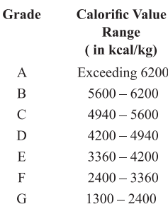
Normally D, E and F coal grades are available to Indian Industry.
The chemical composition of coal has a strong influence on its combustibility.
The properties of coal
are broadly classified as
1. Physical properties
2. Chemical properties
Physical Properties
Heating Value:
The heating value of coal varies from coal field to coal field. The typical GCVs for various coals are
given in the Table 1.4.

Analysis of Coal
There are two methods: ultimate analysis and proximate analysis. The ultimate analysis determines
all coal component elements, solid or gaseous and the proximate analysis determines only the fixed
carbon, volatile matter, moisture and ash percentages. The ultimate analysis is determined in a properly
equipped laboratory by a skilled chemist, while proximate analysis can be determined with a simple
apparatus. It may be noted that proximate has no connection with the word “approximate”.
Measurement of Moisture
Determination of moisture is carried out by placing a sample of powdered raw coal of size 200-micron
size in an uncovered crucible and it is placed in the oven kept at 108 +2 C along with the lid. Then
the sample is cooled to room temperature and weighed again. The loss in weight represents moisture.
Fresh sample of crushed coal is weighed, placed in a covered crucible, and heated in a furnace at 900
+ +15 °C. For the methodologies including that for carbon and ash, refer to IS 1350 part I:1984, part
III, IV. The sample is cooled and weighed. Loss of weight represents moisture and volatile matter.
The remainder is coke (fixed carbon and ash).
Measurement of Carbon and Ash
The cover from the crucible used in the last test is removed and the crucible is heated over the Bunsen
burner until all the carbon is burned. The residue is weighed, which is the incombustible ash. The
difference in weight from the previous weighing is the fixed carbon. In actual practice, Fixed Carbon
or FC derived by subtracting from 100 the value of moisture, volatile matter and ash.
Proximate Analysis
Proximate analysis indicates the percentage by weight of the Fixed Carbon, Volatiles, Ash, and Moisture
Content in coal. The amounts of fixed carbon and volatile combustible matter directly contribute to
the heating value of coal. Fixed carbon acts as a main heat generator during burning. High volatile
matter content indicates easy ignition of fuel. The ash content is important in the design of the furnace
grate, combustion volume, pollution control equipment and ash handling systems of a furnace. A typical
proximate analysis of various coal is given inthe Table 1.5.

Significance of Various Parameters in Proximate Analysis
a) Fixed carbon:
Fixed carbon is the solid fuel left in the furnace after volatile matter is distilled off. It consists mostly
of carbon but also contains some hydrogen, oxygen, sulphur and nitrogen not driven off with the gases.
Fixed carbon gives a rough estimate of heating value of coal.
Volatile Matter
1.Proportionately increases flame length, and helps in easier ignition of coal.
2.Sets minimum limit on the furnace height and volume.
3.Influences secondary air requirement and distribution aspects.
4.Influences secondary oil support
c) Ash Content:
Ash is an impurity that will not burn. Typical range is 5 to 40%
Ash
1. Reduces handling and burning capacity.
2. Increases handling costs.
¢ Affects combustion efficiency and boiler efficiency
3. Causes clinkering and slagging.
d) Moisture Content:
Moisture in coal must be transported, handled and stored. Since it replaces combustible matter, it
decreases the heat content per kg of coal. Typical range is 0.5 to 10%
Moisture
1.Increases heat loss, due to evaporation and superheating of vapour
2.Helps, to a limit, in binding fines.
3.Aids radiation heat transfer.
e) Sulphur Content: Typical range is 0.5 to 0.8% normally.
Sulphur
1.Affects clinkering and slagging tendencies
2.Corrodes chimney and other equipment such as air heaters and economisers
3.Limits exit flue gas temperature.
Chemical Properties
Ultimate Analysis:
The ultimate analysis indicates the various elemental chemical constituents such as Carbon, Hydrogen,
Oxygen, Sulphur, etc. It is useful in determining the quantity of air required for combustion and the
volume and composition of the combustion gases. This information is required for the calculation of
flame temperature and the flue duct design etc. Typical ultimate analyses of various coals are given in
the Table 1.6.


Storage, Handling and Preparation of Coal
Uncertainty in the availability and transportation of fuel necessitates storage and subsequent handling.
Stocking of coal has its own disadvantages like build-up of inventory, space constraints, deterioration
in quality and potential fire hazards. Other minor losses associated with the storage of coal include
oxidation, wind and carpet loss. A 1% oxidation of coal has the same effect as 1% ash in coal, wind
losses may account for nearly 0.5 — 1.0% of the total loss.
The main goal of good coal storage is to minimise carpet loss and the loss due to spontaneous
combustion. Formation of a soft carpet, comprising of coal dust and soil causes carpet loss. On the
other hand, gradual temperature builds up in a coal heap, on account of oxidation may lead to
spontaneous combustion of coal in storage.
The measures that would help in reducing the carpet losses are as follows:
1. Preparing a hard ground for coal to be stacked upon. 2. Preparing standard storage bays out of concrete and brick
In process industry, modes of coal handling range from manual to conveyor systems. It would be
advisable to minimise the handling of coal so that further generation of fines and segregation effects
are reduced.
Preparation of Coal
Preparation of coal prior to feeding into the boiler is an important step for achieving good combustion.
Large and irregular lumps of coal may cause the following problems:
1. Poor combustion conditions and inadequate furnace temperature.
2. Higher excess air resulting in higher stack loss.
3. Increase of unburnts in the ash.
4. Low thermal efficiency.
Proper coal sizing is one of the key measures to ensure efficient combustion. Proper coal sizing, with
specific relevance to the type of firing system, helps towards even burning, reduced ash losses and
better combustion efficiency.
Coal is reduced in size by crushing and pulverizing. Pre-crushed coal can be economical for smaller
units, especially those which are stoker fired. In a coal handling system, crushing is limited to a top
size of 6 or 4mm. The devices most commonly used for crushing are the rotary breaker, the roll crusher
and the hammer mill.
It is necessary to screen the coal before crushing, so that only oversized coal is fed to the crusher. This
helps to reduce power consumption in the crusher. Recommended practices in coal crushing are:
1. Incorporation of a screen to separate fines and small particles to avoid extra fine generation in
crushing.
2. Incorporation of a magnetic separator to separate iron pieces in coal, which may damage the
crusher.
The Table 1.8 gives the proper size of coal for various types of firing systems.

(b) Conditioning of Coal
The fines in coal present problems in combustion on account of segregation effects. Segregation of
fines from larger coal pieces can be reduced to a great extent by conditioning coal with water. Water
helps fine particles to stick to the bigger lumps due to surface tension of the moisture, thus stopping
fines from falling through grate bars or being carried away by the furnace draft. While tempering the
coal, care should be taken to ensure that moisture addition is uniform and preferably done in a moving
or falling stream of coal.
If the percentage of fines in the coal is very high, wetting of coal can decrease the percentage of unburnt carbon and the excess air level required to be supplied for combustion. Table 1.9 shows the extent of wetting, depending on the percentage of fines in coal.

(c) Blending of Coal
In case of coal lots having excessive fines, it is advisable to blend the predominantly lumped coal with
lots containing excessive fines. Coal blending may thus help to limit the extent of fines in coal being
fired to not more than 25%. Blending of different qualities of coal may also help to supply a uniform
coal feed to the boiler.
The proximate and ultimate analysis of various coal is given in Table 1.10 and 1.11.

Properties of Gaseous Fuels
Gaseous fuels in common use are liquefied petroleum gases (LPG), Natural gas, producer gas, blast
furnace gas, coke oven gas etc. The calorific value of gaseous fuel is expressed in kilo Calories per
normal cubic meter (kcal/Nm*) i.e. at normal temperature (20 °C) and pressure (760 mm Hg)
Calorific Value
Since most gas combustion appliances cannot utlilize the heat content of the water vapour, gross
calorific value is of little interest. Fuel should be compared based on the net calorific value. This is
especially true for natural gas, since increased hydrogen content results in high water formation during
combustion.
Typical physical and chemical properties of various gaseous fuels are given in Table 1.12.

LPG
LPG is a predominant mixture of propane and Butane with a small percentage of unsaturates (Propylene
and Butylene) and some lighter C, as well as heavier C, fractions. Included in the LPG range are
propane (C,H,), Propylene (C,H,), normal and iso-butane (C,H,,) and Butylene (C,H,).
47710
LPG may be defined as those hydrocarbons, which are gaseous at normal atmospheric pressure, but
may be condensed to the liquid state at normal temperature, by the application of moderate pressures.
Although they are normally used as gases, they are stored and transported as liquids under pressure
for convenience and ease of handling. Liquid LPG evaporates to produce about 250 times volume of
gas.
LPG vapour is denser than air: butane is about twice as heavy as air and propane about one and half
times as heavy as air. Consequently, the vapour may flow along the ground and into drains sinking to
the lowest level of the surroundings and be ignited at a considerable distance from the source of leakage.
In still air vapour will disperse slowly. Escape of even small quantities of the liquefied gas can give
rise to large volumes of vapour / air mixture and thus cause considerable hazard. To aid in the detection
of atmospheric leaks, all LPG’s are required to be odorized. There should be adequate ground level
ventilation where LPG is stored. For this very reason LPG cylinders should not be stored in cellars or
basements, which have no ventilation at ground level.
Natural Gas
Methane is the main constituent of Natural gas and accounting for about 95% of the total volume.
Other components are: Ethane, Propane, Butane, Pentane, Nitrogen, Carbon Dioxide, and traces of
other gases. Very small amounts of sulphur compounds are also present. Since methane is the largest
component of natural gas, generally properties of methane are used when comparing the properties of
natural gas to other fuels.
Natural gas is a high calorific value fuel requiring no storage facilities. It mixes with air readily and
does not produce smoke or soot. It has no sulphur content. It is lighter than air and disperses into
air easily in case of leak. A typical comparison of carbon contents in oil, coal and gas is given in the
Table 1.13.

Properties of Agro Residues
The use of locally available agro residues is on the rise. This includes rice husk, coconut shells,
groundnut shells, Coffee husk, Wheat stalk etc. The properties of a few of them are given in the
Tables 1.14 and 1.15.

Biomass Storage, Handling and Preparation
Biomass fuels have low bulk density which results in higher transportation cost. The transportation
cost constitutes a significant portion of the landed cost of biomass. The low bulk density also requires
vast area for storage. A common concern in biomass systems is the difficulty to ensure availability of
any particular type of biomass throughout the entire year. A variety of types of biomass necessitate
different types of collection and handling equipment. Most of the common biomass fuels, such as
Woody biomass, Juliflora, Palm bunches, Jute Sticks, Cotton Stalks, De-oiled bran, Coir pith etc.,
require special types of handling machines, which add up to additional capital investment.
Combustion
Principle of Combustion
Combustion refers to the rapid oxidation of fuel accompanied by the production of heat, or heat
and light. Complete combustion of a fuel is possible only in the presence of an adequate supply of
oxygen.
Oxygen (O,) is one of the most common elements on earth making up 20.9% of our air. Rapid fuel
oxidation results in large amounts of heat. Solid or liquid fuels must be changed to a gas before they
will burn. Usually heat is required to change liquids or solids into gases. Fuel gases will burn in their
normal state if enough air is present.
Most of the 79% of air (that is not oxygen) is nitrogen, with traces of other elements. Nitrogen is
considered to be a temperature reducing dilutant that must be present to obtain the oxygen required
for combustion.
Nitrogen reduces combustion efficiency by absorbing heat from the combustion of fuels and diluting
the flue gases. This reduces the heat available for transfer through the heat exchange surfaces. It also
increases the volume of combustion by-products, which then have to travel through the heat exchanger
and up the stack faster to allow the introduction of additional fuel air mixture.
This nitrogen also can combine with oxygen (particularly at high flame temperatures) to produce oxides
of nitrogen (NO_), which are toxic pollutants.
Carbon, hydrogen and sulphur in the fuel combine with oxygen in the air to form carbon dioxide, water
vapour and sulphur dioxide, releasing 8084 kcal, 28922 kcal & 2224 kcal of heat respectively. Under
certain conditions, Carbon may also combine with Oxygen to form Carbon Monoxide, which results
in the release of a smaller quantity of heat (2430 kcal/kg of carbon) carbon burned to CO, will produce
more heat per pound of fuel than when CO or smoke are produced.

Each kilogram of CO formed means a loss of 5654 kcal of heat (8084-2430).
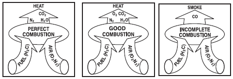
3T’s of Combustion
The objective of good combustion is to release all of the heat in the fuel. This is accomplished by
controlling the “three T’s” of combustion which are (1) Temperature high enough to ignite and maintain
ignition of the fuel, (2) Turbulence or intimate mixing of the fuel and oxygen, and (3) Time sufficient
for complete combustion.
Commonly used fuels like natural gas and propane generally consist of carbon and hydrogen. Water
vapor is a by-product of burning hydrogen. This robs heat from the flue gases, which would otherwise
be available for more heat transfer.
Natural gas contains more hydrogen and less carbon per kg than fuel oils and as such produces more
water vapor. Consequently, more heat will be carried away by exhaust while firing natural gas.
Too much, or too little fuel with the available combustion air may potentially result in unburned fuel
and carbon monoxide generation. A very specific amount of O, is needed for perfect combustion and
some additional (excess) air is required for ensuring complete combustion. However, too much excess
air will result in heat and efficiency losses.
Not all of the heat in the fuel are converted to heat and absorbed by the steam generation equipment.
Usually all of the hydrogen in the fuel is burned and most boiler fuels, allowable with today’s air
pollution standards, contain little or no sulfur. So the main challenge in combustion efficiency
is directed toward unburned carbon (in the ash or incompletely burned gas), which forms CO instead
of CO,.
Combustion of Oil
Heating Oil to Correct Viscosity
When atomizing oil, it is necessary to heat it enough to get the desired viscosity. This temperature
varies slightly for each grade of oil. The lighter oils do not usually require pre-heating. Typical viscosity
at the burner tip (for LAP, MAP & HAP burners) for furnace oil should be 100 Redwood seconds-1
which would require heating the oil to about 105 °C.
Stoichiometric Combustion
The efficiency of a boiler or furnace depends on efficiency of the combustion system. The amount of
air required for complete combustion of the fuel depends on the elemental constituents of the fuel that
is Carbon, Hydrogen, and Sulphur etc. This amount of air is called stoichiometric air. For ideal
combustion process for burning one kg of a typical fuel oil containing 86% Carbon, 12% Hydrogen,
2% Sulphur, theoretically required quantity of air is 14.1 kg. This is the minimum air that would be
required if mixing of fuel and air by the burner and combustion is perfect. The combustion products
are primarily Carbon Dioxide (CO,), water vapor (H, O) and Sulphur Dioxide (SO,), which pass
through the chimney along with the Nitrogen (N,) in the air.
After surrendering useful heat in the heat absorption area of a furnace or boiler, the combustion products or fuel gases leave the system through the chimney, carrying away a significant quantity of heat with them.
Calculation of Stoichiometric Air
The specifications of furnace oil from lab analysis is given below:

GCV of fuel : 10880 kcal/kg
Calculation for Requirement of Theoretical Amount of Air
Considering a sample of 100 kg of furnace oil. The chemical reactions are:

12 kg of carbon requires 32 kg of oxygen to form 44 kg of carbon dioxide therefore 1 kg of carbon
requires 32/12 kg i.e 2.67 kg of oxygen
(85.9) C + (85.9 x 2.67)0, —» 314.97C0,

kg of hydrogen requires 32 kg of oxygen to form 36 kg of water, therefore 1 kg of hydrogen requires
32/4 kg 1.e 8 kg of oxygen
(12) H,+(12x8)0, — (12x9)H,O

32 kg of sulphur requires 32 kg of oxygen to form 64 kg of sulphur dioxide, therefore 1 kg of sulphur
requires 32/32 kg i.e | kg of oxygen
(0.5) S +(05x1) O, — 1.0 So,
Total Oxygen required = 325.57 kg
(229.07+96+0.5)
Oxygen already present in
100 kg fuel (given) = 0.7 kg
Additional Oxygen Required = 325.57 — 0.7
= 324.87 kg
Therefore quantity of dry airreqd. = (324.87) / 0.23
(air contains 23% oxygen by wt.)
= 1412.45 kg of air
Theoretical Air required = (1412.45) / 100
= 14.12 kg of air / kg of fuel
Calculation of theoretical CO, content in flue gases
Nitrogen in flue gas = 1412.45 — 324.87 + 0.5
=1088.08 kg
Theoretical CO,% in dry flue gas by volume is calculated as below :
Moles of CO, in flue gas = (314.97)/44 = 7.16
Moles of N, in flue gas (1088.08) /28 = 38.86
Moles of SO, in flue gas 1/64 = 0.016


= 1088.08 + 570
1658.08 kg
Determination of Actual CO,% by calculation in dry flue gas by volume
Moles of CO, in flue gas = = 314.97/44 = 7.16
Moles of SO, in flue gas = 1/64=0.016
Moles of O, in flue gas = 170.23 /32 =5.32
Moles of N, in flue gas = 1658.08 / 28 = 59.22

Optimizing Excess Air and Combustion
For complete combustion of every one kg of fuel oil 14.1 kg of air is needed. In practice, mixing is
never perfect, a certain amount of excess air is needed to complete combustion and ensure that release
of the entire heat contained in fuel oil. If too much air than what is required for completing combustion
were allowed to enter, additional heat would be lost in heating the surplus air to the chimney temperature.
This would result in increased stack losses. Less air would lead to the incomplete combustion and
smoke. Hence, there is an optimum excess air level for each type of fuel.
Control of Air and Analysis of Flue Gas
Thus in actual practice, the amount of combustion air required will be much higher than optimally
needed. Therefore some of the air gets heated in the furnace boiler and leaves through the stack without
participating in the combustion
Chemical analysis of the gases is an objective method that helps in achieving finer air control. By
measuring carbon dioxide (CO,) or oxygen (O,) in flue gases by continuous recording instruments or
Orsat apparatus or portable fyrite, the excess air level as well as stack losses can be estimated with the
graph as shown in Figure 1.2 and Figure 1.3. The excess air to be supplied depends on the type of fuel
and the firing system. For optimum combustion of fuel oil, the CO, or O, in flue gases should be
maintained at 14 -15% in case of CO, and 2-3% in case of O,.

Oil Firing Burners
The burner is the principal device for the firing of fuel. The primary function of burner is to atomise
fuel to millions of small droplets so that the surface area of the fuel is increased enabling intimate
contact with oxygen in air. The finer the fuel droplets are atomised, more readily will the particles
come in contact with the oxygen in the air and burn.
Normally, atomisation is carried out by primary air and completion of combustion is ensured by
secondary air. Burners for fuel oil can be classified on the basis of the technique to prepare the fuel
for burning i.e. atomisation.
Figure 1.4 shows a simplified burner head. The air is brought into the head by means of a forced draft
blower or fan. The fuel is metered into the head through a series of valves. In order to get proper
combustion, the air molecules must be thoroughly mixed with the fuel molecules before they actually
burn. The air in the center is the primary air used for atomization and the one surrounding is the
secondary air which ensures complete combustion.

The mixing is achieved by burner parts designed to create high turbulence. If insufficient turbulence
is produced by the burner, the combustion will be incomplete and samples taken at the stack will reveal
carbon monoxide as evidence.
Since the velocity of air affects the turbulence, it becomes harder and harder to get good fuel and air
mixing at higher turndown ratios since the air amount is reduced. Towards the highest turndown ratios
of any burner, it becomes necessary to increase the excess air amounts to obtain enough turbulence to
get proper mixing. The better burner design will be one that is able to properly mix the air and fuel at
the lowest possible air flow or excess air.
An important aspect to be considered in selection of burner is turndown ratio. Turndown ratio is the
relationship between the maximum and minimum fuel input without affecting the excess air level. For
example, a burner whose maximum input is 250,000 kcal and minimum rate is 50,000 kcal, has a
“Turn-Down Ratio’ of 5 to 1.
Combustion of Coal
Features of coal combustion
1 kg of coal will typically require 7-8 kg of air depending upon the carbon, hydrogen, nitrogen, oxygen and sulphur content for complete combustion. This air is also known as theoretical or stochiometric air.
If for any reason the air supplied is inadequate, the combustion will be incomplete. The result is poor

generation of heat with some portions of carbon remaining unburnt (black smoke) and forming carbon
monoxide instead of carbon dioxides.
As in the case of oil, coal cannot be burnt with stochiometric quantity of air. Complete combustion is
not achieved unless an excess of air is supplied.
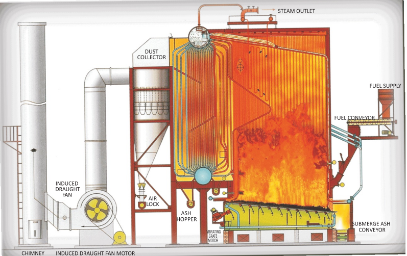
The excess air required for coal combustion depends on the type of coal firing equipment. Hand fired
boilers use large lumps of coal and hence need very high excess air. Stoker fired boilers as shown in
the Figure 1.5 use sized coal and hence requires less excess air. Also in these systems primary air
is supplied below the grate and secondary air is supplied over the grate to ensure complete
combustion.
Fluidised bed combustion in which turbulence is created leads to intimate mixing of air and fuel
resulting in further reduction of excess air. The pulverized fuel firing in which powdered coal is fired
has the minimum excess air due to high surface area of coal ensuring complete combustion
Clinker formation
Clinker is a mass of rough, hard, slag-like material formed during combustion of coal due to low fusion
temperature of ash present in coal. Presence of silica, calcium oxide, magnesium oxides etc. in ash
lead to a low fusion temperature. Typically Indian coals contain ash fusion temperature as low as
1100 °C. Once clinker is formed, it has a tendency to grow. Clinker will stick to a hot surface rather
than a cold one and to a rough surface rather than a smooth one.
Combustion of Gas
Combustion Characteristics of Natural Gas
The stoichiometric ratio for natural gas (and most gaseous fuels) is normally indicated by volume.
The air to natural gas (stoichiometric) ratio by volume for complete combustion vary between 9.5:1
to 10:1
Natural gas is essentially pure methane, CH,. Its combustion can be represented as follows:
CH, +20, = CO, + 2H,O
So for every 16 kgs of methane that are consumed, 44 kgs of carbon dioxide are produced. (Remember
that the atomic weights of carbon, oxygen and hydrogen are 12, 16 and 1, respectively.)
Methane burns, when mixed with the proper amount of air and heated to the combustion temperature.
Figure 1.6 shows the process with the amount of air and fuel required for perfect combustion.

The important thing in all gas-burning devices is a correct =
air-and-gas mixture at the burner tip. Low-pressure burners ¥ ‘a.
(Figure 1.7), using gas at a pressure less than 0.15 kg/cm? (2 tof boas fi &
psi), are usually of the multi-jet type, in which gas from a a
manifold is supplied to a number of small single jets, or & \\
circular rows of small jets, centered in or discharging around
the inner circumference of circular air openings in a block
of some heat-resisting material. The whole is encased in a rectangular cast-iron box, built into the boiler setting and
having louver doors front to regulate the air supply. Draft may be natural, induced, or forced.


Combustion of Biomass
Biomass can be converted into energy (heat or electricity) or energy carriers (charcoal, oil, or gas)
using both thermochemical and biochemical conversion technologies. Combustion is the most developed
and most frequently applied process used for solid biomass fuels because of its low costs and high
reliability. During combustion, the biomass first loses its moisture at temperatures up to 100°C, using heat from
other particles that release their heat value. As the dried particle heats up, volatile gases containing
hydrocarbons, CO, CH4 and other gaseous components are released. In a combustion process, these
gases contribute about 70% of the heating value of the biomass. Finally, char oxidises and ash remains.
The combustion installation needs to be properly designed for a specific fuel type in order to guarantee
adequate combustion quality and low emissions.
In order to reduce its moisture content, freshly harvested wood is often left outside for a number of
weeks before it is chipped and fed to a combustion plant.
Different biomass combustion systems are available for industrial purposes. Broadly, they can be
defined as fixed-bed combustion, fluidised bed combustion, and dust combustion.
Fluidised bed combustion
Fixed-bed combustion:
Fixed-bed combustion systems include grate furnaces and underfeed stokers. Primary air passes through
a fixed bed, where drying, gasification, and charcoal combustion take place in consecutive stages. The
combustible gases are burned in a separate combustion zone using secondary air. Grate furnaces are
appropriate for burning biomass fuels with high moisture content, different particle sizes, and high
ash content. The design and control of the grate are aimed at guaranteeing smooth transportation and
even distribution of the fuel and a homogeneous primary air supply over the whole grate surface.
Irregular air supply may cause slagging, and higher amounts of fly ash, and may increase the oxygen
needed for complete combustion. Load changes can be achieved more easily and quickly than in grate
furnaces because there is better control of the fuel supply.
In a fluidised bed, biomass fuel is burned in a self-mixing suspension of gas and solid bed material
(usually silica sand and dolomite) in which air for combustion enters from below. Depending on the
fluidisation velocity, bubbling and circulating fluidised bed combustion can be distinguished.
The intense heat transfer and mixing provide good conditions for complete combustion with low excess
air demand. The low excess air amounts required reduce the flue gas volume flow and increase
combustion efficiency. Fluid bed combustion plants are of special interest for largescale applications
(normally exceeding 30 MWth). For smaller plants, fixed bed systems are usually more cost-effective.
One disadvantage is the high dust loads in the flue gas, which make efficient dust precipitators and
boiler cleaning systems necessary. Bed material is also lost with the ash, making it necessary to
periodically add new bed material.
Dust combustion Dust combustion is suitable for fuels available as small, dry particles such as wood dust. A mixture of
fuel and primary combustion air is injected into the combustion chamber. Combustion takes place
while the fuel is in suspension; the transportation air is used as primary air. Gas burnout is achieved
after secondary air addition. An auxiliary burner is used to start the furnace. When the combustion
temperature reaches a certain value, biomass injection starts and the auxiliary burner is shut down.
Due to the explosion-like gasification process of the biomass particles, careful fuel feeding is essential.
Fuel gasification and charcoal combustion take place at the same time because of the small particle size. Therefore, quick load changes and efficient load control can be achieved. Since the fuel and air
are well-mixed, only a small amount of excess air is required. This results in high combustion
efficiencies.
Draft System
The function of draft in a combustion system is to exhaust the products of combustion into the
atmosphere. The draft systems can be classified into two types namely Natural and Mechanical
Draft.
It is the draft produced by a chimney alone. It is caused by the difference in weight
between the column of hot gas inside the chimney and column of outside air of the same height and
cross section. Being much lighter than outside air, chimney flue gas tends to rise, and the heavier
outside air flows in through the ash pit to take its place. It is usually controlled by hand-operated
dampers in the chimney and breeching connecting the boiler to the chimney. Here no fans or blowers
are used. The products of combustion are discharged at such a height that it will not be a nuisance to
the surrounding community.
Mechanical Draft : It is the draft artificially produced by fans. Three basic types of draft systems
available are:
Balanced Draft : Forced-draft (F-D) fan (blower) pushes air into the furnace and an induced-draft
(I-D) fan draws gases into the chimney thereby providing draft to remove the gases from the boiler.
Here the pressure is maintained between 0.05 to 0.10 in. of water gauge below atmospheric pressure
in the case of boilers and slightly positive for reheating and heat treatment furnaces.
Induced Draft : An induced-draft fan draws enough draft for flow into the furnace, causing the products
of combustion to discharge to atmosphere. Here the furnace is kept at a slight negative pressure below
the atmospheric pressure so that combustion air flows through the system.
Forced Draft : The Forced draft system uses a fan to deliver the air to the furnace, forcing combustion
products to flow through the unit and up the stack.
Combustion Controls
Combustion controls assist the burner in regulation of fuel supply, air supply, (fuel to air ratio), and
removal of gases of combustion to achieve optimum boiler efficiency. The amount of fuel supplied
to the burner must be in proportion to the steam pressure and the quantity of steam required.
The combustion controls are also necessary as safety device to ensure that the boiler operates
safely.
Various types of combustion controls in use are:
ON/OFF Control
The simplest control, ON/OFF control means that either the burner is firing at full rate or it is OFF.
This type of control is limited to small boilers.
High/Low/OFF Control
Slightly more complex is HIGH/LOW/OFF system where the burner has two firing rates. The burner
operates at slower firing rate and then switches to full firing as needed. Burner can also revert to low
firing position at reduced load. This control is fitted to medium sized boilers.
Modulating Control
The modulating control operates on the principle of matching the steam pressure demand by altering
the firing rate over the entire operating range of the boiler. Modulating motors use conventional
mechanical linkage or electric valves to regulate the primary air, secondary air, and fuel supplied to
the burner. Full modulation means that boiler keeps firing, and fuel and air are carefully matched over
the whole firing range to maximize thermal efficiency.
Solved Example:
For combustion of 500 lit/hr of furnace oil, estimate combustion air quantity per hour with 20% excess
air. Specific gravity of furnace oil 0.95. (Fuel analysis: C - 84%, H, -12%, S - 3%, O, - 1%).

------------------------
Chapter 2
Comments
Post a Comment