Energy efficiency in Thermal utilities
Ch-4 (Furnaces)
A furnace is an equipment to melt metals for casting or heat materials for change of shape (Rolling, forging etc) or change of properties (heat treatment).
4.1 Types and Classification of Different Furnaces
Based on the method of generating heat, furnaces are broadly classified into two types namely
1.combustion type (using fuels) and
2.electric type.
The combustion type furnace can be broadly classified oil fired, coal fired or gas fired, depending upon the kind of combustion. Based on the code of charging of material furnaces can be classified as
(i) Intermittent or Batch type furnace or Periodical furnace and
(ii) Continuous furnace. Based on mode of waste heat recovery as recuperative and regenerative furnaces.
Another type of furnace classification is made based on mode of heat transfer, mode of charging and mode of heat recovery as shown in the Figure 4.1 below.
The electric furnaces can be broadly classified as resistance type for heating and induction and are for melting of metals.
Characteristics of an Efficient Furnace
Furnace should be designed so that in a given time, as much of material as possible can be heated to a uniform temperature as possible with the least possible fuel and labour. To achieve this end, the following parameters can be considered. Determination of the quantity of heat to be imparted to the material or charge. Liberation of sufficient heat within the furnace to heat the stock and overcome all heat losses. Transfer of available part of that heat from the furnace gases to the surface of the heating stock. Equalisation of the temperature within the stock. Reduction of heat losses from the furnace to the minimum possible extent.
Furnace Energy Supply
Since the products of flue gases directly contact the stock, type of fuel chosen is of importance. For example, some materials will not tolerate sulphur in the fuel. Also use of solid fuels will generate particulate matter, which will interfere with the stock place inside the furnace. Hence, vast majority of the furnaces use liquid fuel, gaseous fuel or electricity as energy input. Electricity is used in induction and arc furnaces for melting steel and cast iron. Non-ferrous melting utilizes oil as fuel.
Oil Fired Furnace
Furnace oil is the major fuel used in oil fired furnaces, especially for reheating and heat treatment of materials. LDO is used in furnaces where presence of sulphur is undesirable. The key to efficient furnace operation lies in complete combustion of fuel with minimum excess air. Furnaces operate with efficiencies as low as 7% as against upto 90% achievable in other combustion equipment such as boiler. This is because of the high temperature at which the furnaces have to operate to meet the required demand. For example, a furnace heating the stock to 1200 °C will have its exhaust gases leaving at least at 1200 °C resulting in a huge heat loss through the stack. However, improvements in efficiencies have been brought about by methods such as preheating of stock, preheating of combustion air and other waste heat recovery systems.
Typical Furnace System
i) Forging Furnaces
The forging furnace is used for preheating billets and blooms to attain a 'forge' temperature. The furnace temperature is maintained at around 1200 to 1250 °C. Forging furnaces use an open fireplace system and most of the heat is transmitted by radiation. The total operating cycle can be divided into (a) heat up time
(b) soaking time and
(c) forging time.
Normally, large pieces are soaked for 4 to 6 hrs inside the furnace to attain uniform temperaturethroughout the cross-section of the material. The actual soaking time varies with the type and thickness of the material. The completely soaked material is withdrawn from furnace to the hammer to be forged as required. Larger pieces may have to be reheated several times. A typical forging furnaces is illustrated in Figure 4.2.
Figure 4.2 Forging Furnace
The charging and discharging of the material is done manually and this results in significant heat loss during the forging operation. Forging furnaces use an open fireplace system and most of the heat is transmitted by radiation. Specific fuel consumption depends upon the type of material and number of ‘reheats’ required.
ii) Rerolling Mill Furnace
a) Batch type
A box type furnace is employed for batch type rerolling mill. The furnace is basically used for heating up scrap, small ingots and billets weighing 2 to 20 kg for rerolling. The charging and discharging of the ‘material’ is done manually and the final product is in the form of rods, strips etc. The operating temperature is about 1200°C. The total cycle time can be further categorized into heat-up time and rerolling time. During heat-up time the material gets heated upto the required temperature and is removed manually for rerolling. The average output from these furnaces varies from 10 to 15 tonnes / day.
b) Continuous Pusher Type
The process flow and operating cycles of a continuous pusher type is the same as that of the batch furnace. The operating temperature is about 1250°C. Generally, these furnaces operate 8 to 10 hourswith an output of 50 to 100 tonnes per day. The material or stock recovers a part of the heat in flue gases as it moves down the length of the furnace. Heat absorption by the material in the furnace is slow, steady and uniform throughout the cross-section compared with batch type.
iii) Continuous Steel Reheating Furnaces
The main function of a reheating furnace is to raise the temperature of a piece of steel, typically to between 900 °C and 1250 °C, until it is plastic enough to be pressed or rolled to the desired section, size or shape, The furnace must also meet specific requirements and objectives in terms of stock heating rates for metallurgical and productivity reasons. In continuous reheating, the steel stock forms a continuous flow of material and is heated to the desired temperature as it travels through the furnace. All furnaces possess the features shown in Figure 4.3
1. A refractory chamber constructed of insulating materials for retaining heat at the high operating temperatures.
2.A hearth to support or carry the steel. This can consist of refractory materials or an arrangement of metallic supports that may be water-cooled.
3. Burners that use liquid or gaseous fuels to raise and maintain the temperature in the chamber. Coal or electricity can be used for reheating. A method of removing the combustion exhaust gases from the chamber.
4. A method of introducing and removing the steel from the chamber.
5. These facilities depend on the size and type of furnace, the shape and size of the steel being processed, and the general layout of the rolling mill.
6. Common systems include roller tables, conveyors, charging machines and furnace pushers.
Heat Transfer in Furnaces
The main ways in which heat is transferred to the steel in a reheating furnace are shown in Figure 4.4. In simple terms, heat is transferred to the stock by:
1. Radiation from the flame, hot combustion products and the furnace walls and roof;
2. Convection due to the movement of hot gases over the stock surface.
At the high temperatures employed in reheating furnaces, the dominant mode of heat transfer is wall radiation. Heat transfer by gas radiation is dependent on the gas composition (mainly the carbon dioxide and water vapour concentrations), the temperature and the geometry of the furnace.
Types of Continuous Reheating Furnace
Continuous reheating furnaces are primarily categorised by the method by which stock is transported through the furnace. There are two basic methods:
1.Stock is butted together to form a stream of material that is pushed through the furnace. Such furnaces are called pusher type furnaces.
2.Stock is placed on a moving hearth or supporting structure which transports the steel through the furnace. Such types include walking beam, walking hearth, rotary hearth and continuous recirculating bogie furnaces.
The major consideration with respect to furnace energy use is that the inlet and outlet apertures should be minimal in size and designed to avoid air infiltration.
i) Pusher Type Furnaces
The pusher type furnace is popular in steel industry. It has relatively low installation and maintenance costs compared to moving hearth furnaces. The furnace may have a solid hearth, but it is also possible to push the stock along skids with water-cooled supports that allow both the top and bottom faces of the stock to he heated. The design of a typical pusher furnace design is shown schematically in Figure 4.5.
Pusher type furnaces, however, do have some disadvantages, including:
1. Frequent damage of refractory hearth and skid marks on material.
2. Water cooling energy losses from the skids and stock supporting structure in top and bottom fired furnaces have a detrimental effect on energy use;
3.Discharge must be accompanied by charge:
4. Stock sizes and weights and furnace length are limited by friction and the possibility of stock pile-ups.
5. Allround heating of the stock is not possible.
ii) Walking Hearth Furnaces
The walking hearth furnace (Figure.4.6) allows the stock to be transported through the furnace in discrete steps. Such furnaces have several attractive features, including: simplicity of design, ease of construction, ability to cater for different stock sizes (within limits), negligible water cooling energy losses and minimal physical marking of the stock. The main disadvantage of walking hearth furnaces is that the bottom face of the stock cannot be heated. This can he alleviated to some extent by maintaining large spaces between pieces of stock. Small spaces between the individual stock pieces limits the heating of the side faces and increases the potential for unacceptable temperature differences within the stock at discharge. Consequently, the stock residence time may be long, possibly several hours; this may have an adverse effect on furnace flexibility and the yield may be affected by scaling.
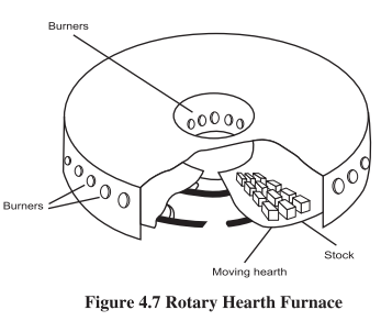
iii) Rotary hearth furnace
The rotary hearth furnace (Figure 4.7) has tended to supersede the re-circulating bogie type. The heating and cooling effects introduced by the bogies are eliminated, so heat storage losses are less. The rotary hearth has, however a more complex design with an annular shape and revolving hearth.
iv) Continuous Recirculating Bogie type Furnaces
These types of moving hearth type furnaces tend to be used for compact stock of variable size and geometry. In bogie furnaces (Figure 4.8), the stock is placed on a bogie with a refractory hearth, which travels through the furnace with others in the form of a train. The entire furnace length is always occupied by bogies. Bogie furnaces tend to be long and narrow and to suffer from problems arising from inadequate sealing of the gap between the bogies and furnace shell, difficulties in removing scale, and difficulties in firing across a narrow hearth width.
v) Walking Beam Furnaces: The walking beam furnace (Figure 4.9) overcomes many of the problems of pusher furnaces and permits heating of the bottom face of the stock. This allows shorter stock heating times and furnace lengths and thus better control of heating rates, uniform stock discharge temperatures and operational flexibility. In common with top and bottom fired pusher furnaces, however, much of the furnace is below the level of the mill; this may be a constraint in some applications.
vi) Cupola Furnace A cupola furnace (Figure 4.10) is tall, cylindrical melting device used in foundries to melt pig iron, cast iron, foundry returns. The charge used in cupola furnace consists of alternate layers of coke,flux and metal (iron). These three components are continuously built into the cupola furnace. The cost commonly used iron with refractory lining - to - coke ratio is 8:1. The flux may be limestone (CaCO,), fluorspar, sodium carbonate or calcium carbide. Limestone .: is the commonly employed flux. The total weight Melting Zone of the flux will be approximately 1/5" the weight peducing Zonet of the coke charge. Sufficient air is passed through combustion Ane the tuyeres for proper combustion of coke.
Melting in Cupola Furnace Cupola furnace works on the counter current principle. As the combustion takes place, the charge materials (coke, flux and metal) will be descending downwards, while the hot gases due to combustion will be ascending upwards. Heat exchange takes place between the rising hot gases and the descending charge thereby melting the metal. The liquid metal drops down, while the coke floats up on top of it.
The flux also melts and reacts with the impurities of the molten metal forming a slag. The slag floats on the surface of the molten metal thereby preventing oxidation of the metal.
Zones of Cupola Furnace
Well zone in Cupola Furnace:-
Well zone in the portion situated between the rammed sand bottom and just below the bottom edge of the tuyeres. The molten metal is occupied in this zone.
Combustion Zone in Cupola Furnace
The combustion zone or oxidizing zone is situated normally 15-30 cm from the bottom edge of the tuyeres. It is in this zone where rapid combustion of coke takes place due to which a lot of heat is generated in the furnace. The combustion is rapid due to the supply of blast air through the tuyeres.
Oxidation of manganese and silicon evolve still more heat. The reactions which take place in this zone are:
C + O, (from air) — CO, + heat
2Mn+O, — 2 MnO + heat
Si+O, > SiO, + heat
The temperature in this zone varies from 155 °C — 185 °C
Reducing zone or protection zone is the portion located from the top of the combustion zone to the top of the coke bed. In this zone, some of the hot CO, gas moving upward through the hot coke gets reduced to CO. In other words, reduction of CO, to CO occurs in this zone. Due to the reducing atmosphere, the charge is protected from oxidation. The reaction taking place in this zone is given by.
CO2 + C (coke) = 2 CO — Heat
Due to the reduction, the temperature reduces to around 1200 °C in this zone.
Melting Zone in Cupola Furnace
The portion located just above the coke bed to the top of the metal (iron) is called the melting zone. The metal starts melting in this zone and trickles down through the coke bed to the well zone. The molten iron while passing down through the reducing zone picks up carbon and the reaction is given by:
3 Fe +2CO + Fe,C+CO,
Preheating zone in Cupola Furnace
The portion occupied from the top surface of the melting zone to the charging door is called ‘Preheating zone’. The hot gases rising upwards from the combustion and reducing zone gives its heat to the charge before passing out of the furnace. Thus, the charge is preheated before descending downwards.
Hot Blast Cupola
The temperature of exhaust gas of a cupola is as high as 800 °C, making it possible to preheat blast air up to as high as 400 °C by heat exchange. In addition, both the sensible and latent heat of exhaust gas can be recycled for preheating blast air by combustion of CO gas included in exhaust gas. When blast air is preheated to 300 °C or higher, the sensible heat of blast air is added to heat input, activating combustion of coke, leading to the rise in combustion temperature.
vii) Induction Furnaces
Induction furnaces are ideal for melting and alloying a wide variety of metals with minimum melt losses, however, little refining of the metal is possible. There are two main types of induction furnace: coreless and channel, the principle of operation of which are the same.
Coreless Induction Furnace
Coreless induction furnace (Figure 4.11) consists of: a water cooled helical coil made of a copper tube, a crucible installed within the coil and supporting shell equipped with trunnions on which the furnace may tilt. Alternating current passing through the coil induces alternating currents in the metal charge loaded to the crucible. These induced currents heat the charge.When the charge is molten, electromagnetic field produced by the coil interacts with the electromagnetic field produced by the induced current.
The resulted force causes stirring effect helping homogenizing the melt composition and the temperature.
The frequency of the alternating current used in induction furnaces may vary from the line frequency (50 Hz or 60 Hz) to high frequency 10,000 Hz The total absolute energy required to melt one tonne of different metals at different molten temperature is given in table 4.1.
The actual consumption of electricity for melting can be measured from the input busbar to the furnace. the difference between Actual and theoretical values will be loss due to conduction, radiation and other losses.
Example — Melting of MLS. scrap
Calculate the furnace efficiency from the data given below
Specific heat - 0.682 kJ/kg °C
Latent heat - 272 kJ/kg
Melting temperature - 1650 °C
Charge temperature - 30°C
Quantity of metal - 1000 kg
Quantity of slag -25kg
Electricity consumed - 625 kWh
Distribution of losses in induction furnace Losses in induction furnace
The theoretical energy require to melt one Ton of steel is 385 TO 400 kWh/Ton. However in actual practice, the specific energy consumption is remarkably higher to 550 - 950 kWh/ton.
1. Power loss in generator / panel = 2-4%
2. Power loss in capacitor Bank = 10-3%
3. Power loss in Crucible = 18-25% (Water cooled cables, Bus bar, and change over switches)
4. Radiation loss 7-9%
Factors affecting the furnace efficiency
The factors, which affect the furnace efficiency, are as under;
o Due to poor maintenance the total production stops sometimes. Higher breakdown results in increasing the’ cost of production.
o Due to low supply voltage the furnace draws less power, causes slow melting and inefficient operation resulting increase in production cost.
o Some time lining material selection is wrong with respect to metal. Basic lining is better conductor of heat compared to acidic lining. Wrong lining selection increases breakdown, Furnace down time and furnace losses, resulting in inefficient operation.
oPoor coordination between melting staff & contractor.
oAbsence of material handling equipment
oPoor molding efficiency, so furnace on hold
o Poor quality scrap, reducing lining life, takes more time to melt.
oAbsence of thermal insulation between lining & coil.
Hot Air Generator
Hot air at a wide range of temperatures and pressures is produced for applications like foundry sand drying, shell sand coating, core drying rooms or ovens, drying and processing of ores and minerals, food processing, tea drying, seed drying and paint drying. Furnace oil, HSD, LDO, LPG or natural gas may be used. Hot air generators supply air heated to elevated temperature by mixing it with products of combustion from a burner.
The hot air generator consists of an inner refractory chamber, venturi section where hot products of combustion mix with dilution air, and outlet section. The combustion chamber is lined with firebrick, while the mixing chamber and the outlet section are lined with insulation brick. Air and oil pipelines required for combustion are included.
The combustion equipment comprises of burner with burner block, mounting plate, isolating valve, and oil pumping and heating unit.
4.2 Performance Evaluation of a Typical Fuel Fired Furnace
Thermal efficiency of process heating equipment, such as furnaces, ovens, heaters, and kilns is the ratio of heat delivered to a material and heat supplied to the heating equipment. In the context of performance assessment of furnaces, the concepts of excess air and computation of various heat losses, as in case of boilers, could be applied, but there exist several additionalities and features, that differentiate furnace efficiency from boiler efficiency. Whereas boiler efficiency of 70- 90% is achievable, furnace efficiencies at times are as low as 5%, while with favorable condition, like good design, loading, Waste heat recovery O&M practices, efficiencies up to 60% & higher can be achieved. The reasons for low furnace efficiency include;
1.High stack temperature and excess air levels.
2.Low capacity utilization/ hearth loading.
3.Radiation losses due to opening.
4.Surface heat losses.
5.Batch operation involving heating, cooling and soaking cycles.
One reason for the difference in thermal efficiency between boiler furnaces and industrial furnaces lies in the final temperature of the material being heated. Gases can give up heat to the charge only as long as they are hotter than the charge. In consequence, the flue gases must leave industrial furnace at a very high temperature except for a short time after a cold start.
The purpose of a heating process is to introduce a certain amount of thermal energy into a product, raising it to a certain temperature to prepare it for additional processing or change its properties. To carry this out, the product is heated in a furnace. This results in energy losses in different areas and forms as shown in sankey diagram Figure 4.12. For most heating equipment, a large amount of the heat supplied is wasted in the form of exhaust gases. These furnace losses include:
1.Heat storage in the furnace structure
2.Losses from the furnace outside walls or structure
3.Heat transported out of the furnace by the load conveyors, fixtures, trays, etc.
4.Radiation losses from openings, hot exposed parts, etc.
5.Heat carried by the cold air infiltration into the furnace
6.Heat carried by the excess air used in the burners.
Stored heat loss:
First, the metal structure and insulation of the furnace must be heated so their interior surfaces are about the same temperature as the product they contain. This stored heat is held in the structure until the furnace shuts down, then it leaks out into the surrounding area. The more frequently the furnace is cycled from cold to hot and back to cold again, the more frequently this stored heat must be replaced. Fuel is consumed with no useful output.
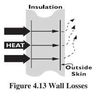
Wall losses: Additional heat losses take place while the furnace is in production. Wall or transmission losses are caused by the conduction of heat through the walls, roof, and floor of the heating device, as shown in Figure 4.13. Once that heat reaches the outer skin of the furnace and radiates to the surrounding area or is carried away by air currents, it must be replaced by an equal amount taken from the combustion gases. This process continues as long as the furnace is at an elevated temperature.
Material handling losses:
Many furnaces use equipment to convey the work into and out of the heating chamber, and this can also lead to heat losses. Conveyor belts or product hangers that enter the heating chamber cold and leave it at higher temperatures drain energy from the combustion gases. In car bottom furnaces, the hot car structure gives off heat to the room each time it rolls out of the furnace to load or remove work. This lost energy must be replaced when the car is returned to the furnace.
Cooling media losses.
Water or air cooling protects rolls, bearings, and doors in hot furnace environments, but at the cost of lost energy. These components and their cooling media (water, air, etc.) become the conduit for additional heat losses from the furnace. Maintaining an adequate flow of cooling media is essential, but it might be possible to insulate the furnace and load from some of these losses.
Radiation (opening) losses.
Furnaces and ovens operating at temperatures above 540°C might have significant radiation losses, as shown in Figure 4.14 Hot surfaces radiate energy to nearby colder surfaces, and the rate of heat transfer increases with the fourth power of the surface’s absolute temperature. Anywhere or anytime there is an opening in the furnace enclosure, heat is lost by radiation, often at a rapid rate.
Waste-gas losses.
Waste-gas loss, also known as flue gas or stack loss, is made up of the heat that cannot be removed from the combustion gases inside the furnace. The reason is heat flows from the higher temperature source to the lower temperature heat receiver.
Air infiltration. Excess air does not necessarily enter the furnace as part of the combustion air supply. It can also infiltrate from the surrounding room if there is a negative pressure in the furnace. Because of the draft effect of hot furnace stacks, negative pressures are fairly common, and cold air slips past leaky door seals, cracks and other openings in the furnace. Figure 4.15 illustrates air infiltration from outside the furnace. Every time the door is opened, considerable amount of heat is lost. Economy in fuel can be achieved if the total heat that can be passed on to the stock is as large as possible.
The efficiency of furnace can be assessed by measuring the amount of heat added to the stock and the heat in the fuel consumed, on a batch/day basis as relevant
Indirect Method
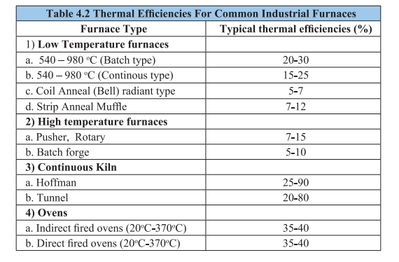
Similar to the method of evaluating boiler efficiency by indirect method (Heat Balance Method), furnace efficiency can also be calculated by indirect methods. Furnace efficiency is calculated after subtracting sensible heat loss in flue gas, loss due to moisture in flue gas, heat loss due to openings in furnace, heat loss through furnace skin and other unaccounted losses. The detailed calculation by indirect method (Heat balance method) is given in Chapter — 2 of Book — 4. Typical thermal efficiencies for common industrial furnaces are given in Table: 4.2
The instruments required for carrying out performance evaluation in a furnace is given in the Table 4.3.
4.3. General Fuel Economy Measures in Furnaces Typical energy efficiency measures for an industry with furnace are:
1) Complete combustion with minimum excess air
2) Correct heat distribution
3) Operating at the desired temperature
4) Reducing heat losses from furnace openings
5) Maintaining correct amount of furnace draught
6) Optimum capacity utilization
7) Waste heat recovery from the flue gases
8) Minimum refractory losses
9) Use of Ceramic Coatings
1. Complete Combustion with Minimum Excess Air:
The amount of heat lost in the flue gases (stack losses) depends upon amount of excess air. In the case of a furnace carrying away flue gases at 900°C, % heat lost is shown in table 4.4:
To obtain complete combustion of fuel with the minimum amount of air, it is necessary to control air infiltration, maintain pressure of combustion air, fuel quality and excess air monitoring. Higher excess air will reduce flame temperature, furnace temperature and heating rate. On the other hand, if the excess air is less, then unburnt components in flue gases will increase and would be carried away in the flue gases through stack. The figure 4.16 also indicates relation between air ratio and exhaust gas loss.

The optimization of combustion air is the most attractive and economical measure for energy conservation. The impact of this measure is higher when the temperature of furnace is high. Air ratio is the value that is given by dividing the actual air amount by the theoretical combustion air amount, and it represents the extent of excess of air. If a reheating furnace is not equipped with an automatic air/fuel ratio controller, it is necessary to periodically sample gas in the furnace and measure its oxygen contents by a gas analyzer. The Figure 4.17 shows a typical example of a reheating furnace equipped with an automatic air/fuel ratio controller.
More excess air also means more scale losses, which is equally a big loss in terms of money.
2. Proper Heat Distribution:
Furnace design should be such that in a given time, as much of the stock could be heated uniformly to a desired temperature with minimum fuel firing rate.
Following care should be taken when using burners, for proper heat distribution:
1) The flame should not touch any solid object and should propagate clear of any solid object. Any obstruction will de atomise the fuel particles thus affecting combustion and create black smoke. If flame impinges on the stock, there would be increase in scale losses (Refer Figures 4.18 and 4.19).
ii) If the flames impinge on refractories, the incomplete combustion products can settle and react with the refractory constituents at high flame temperatures.
il) The flames of different burners in the furnace should stay clear of each other. If they intersect, inefficient combustion would occur. It is desirable to stagger the burners on the opposite sides.
iv) The burner flame has a tendency to travel freely in the combustion space just above the material. In small furnaces, the axis of the burner is never placed parallel to the hearth but always at an upward angle. Flame should not hit the roof.
v) The larger burners produce a long flame, which may be difficult to contain within the furnace walls. More burners of less capacity give better heat distribution in the furnace and also increase furnace life.
vi) For small furnaces, it is desirable to have a long flame with golden yellow colour while firing furnace oil for uniform heating. The flame should not be too long that it enters the chimney or comes out through the furnace top or through doors. In such cases, major portion of additional fuel is carried away from the furnace.
3. Maintaining Optimum Operating Temperature of Furnace :
It is important to operate the furnace at optimum temperature. The operating temperatures of various furnaces are given in table 4.5.
Operating at too high temperatures than optimum causes heat loss, excessive oxidation, decarbonization as well as over-stressing of the refractories. These controls are normally left to
operator judgment, which is not desirable. To avoid human error, on/off controls should be provided.
4. Prevention of Heat Loss through Openings
Heat loss through openings consists of the heat loss by direct radiation through openings and the heat loss caused by combustion gas that leaks through openings. The heat loss from an opening can also be calculated using the following formula:
If the furnace pressure is slightly higher than outside air pressure (as in case of reheating furnace) during its operation, the combustion gas inside may blow off through openings and heat is lost with that. But damage is more, if outside air intrudes into the furnace, making temperature distribution uneven and oxidizing billets. This heat loss is about 1% of the total quantity of heat generated in the furnace, if furnace pressure is controlled properly.
5. Control of furnace draft:
If negative pressures exist in the furnace, air infiltration is liable to occur through the cracks and openings thereby affecting air- fuel ratio control. Tests conducted on apparently airtight furnaces have shown air infiltration up to the extent of 40%. Neglecting furnaces pressure could mean problems of cold metal and non-uniform metal temperatures, which could affect subsequent operations like forging and rolling and result in increased fuel consumption. For optimum fuel consumption, slight positive pressure should be maintained in the furnace as shown in Figure 4.20. Ex-filtration is less serious than infiltration. Some of the associated problems with ex filtration are leaping out of flames, overheating of the furnace refractories leading to reduced brick life, increased furnace maintenance, burning out of ducts and equipments attached to the furnace, etc. In addition to the proper control on furnace pressure, it is important to keep the openings as small as possible and to seal them in order to prevent the release of high temperature gas and intrusion of outside air through openings such as the charging inlet, extracting outlet and peephole on furnace walls or the ceiling.

6. Optimum Capacity Utilization:
One of the most vital factors affecting efficiency is loading. There is a particular loading at which the furnace will operate at maximum thermal efficiency. If the furnace is under loaded a smaller fraction of the available heat in the working chamber will be taken up by the load and therefore efficiency will be low.
The best method of loading is generally obtained by trial-noting the weight of material put in at each charge, the time it takes to reach temperature and the amount of fuel used. Every endeavour should be made to load a furnace at the rate associated with optimum efficiency although it must be realised that limitations to achieving this are sometimes imposed by work availability or other factors beyond control.
The loading of the charge on the furnace hearth should be arranged so that
1.Itreceives the maximum amount of radiation from the hot surfaces of the heating chambers and the flames produced.
2.The hot gases are efficiently circulated around the heat receiving surfaces
Stock should not be placed in the following position
1.In the direct path of the burners or where flame impingement is likely to occur.
2.In an area which is likely to cause a blockage or restriction of the flue system of the furnace.
3.Close to any door openings where cold spots are likely to develop.
The other reason for not operating the furnace at optimum loading is the mismatching of furnace dimension with respect to charge and production schedule.
In the interests of economy and work quality the materials comprising the load should only remain in the furnace for the minimum time to obtain the required physical and metallurgical requirements. When the materials attain these properties they should be removed from the furnace to avoid damage and fuel wastage. The higher the working temperature, higher is the loss per unit time. The effect on the materials by excessive residence time will be an increase in surface defects due to oxidation. The rate of oxidation is dependent upon time, temperature, as well as free oxygen content. The possible increase in surface defects can lead to rejection of the product. It is therefore essential that coordination between the furnace operator, production and planning personnel be maintained.
Optimum utilization of furnace can be planned at design stage. Correct furnace for the jobs should be selected considering whether continuous or batch type furnace would be more suitable. For a continuous type furnace, the overall efficiency will increase with heat recuperation from the waste gas stream. If only batch type furnace is used, careful planning of the loads is important. Furnace should be recharged as soon as possible to enable use of residual furnace heat.
7. Waste Heat Recovery from Furnace Flue Gases:
In any industrial furnace the products of combustion leave the furnace at a temperature higher than the stock temperature. Sensible heat losses in the flue gases, while leaving the chimney, carry 35 to 55 per cent of the heat input to the furnace. The higher the quantum of excess air and flue gas temperature, the higher would be the waste heat availability.
Waste heat recovery should be considered after all other energy conservation measures have been taken. Minimizing the generation of waste heat should be the primary objective.
The sensible heat in flue gases can be generally recovered by the following methods. (Figure 4.21)
1.Charge (stock) preheating,
2.Preheating of combustion air,
3.Utilizing waste heat for other process (to generate steam or hot water by a waste heat boiler)
Charge Pre-heating
When raw materials are preheated by exhaust gases before being placed in a heating furnace, the amount of fuel necessary to heat them in the furnace is reduced. Since raw materials are usually at room temperature, they can be heated sufficiently using high-temperature gas to reduce fuel consumption rate.
Preheating of Combustion AirFor a long time, the preheating of combustion air using heat from exhaust gas was not used except for large boilers, metal-heating furnaces and high-temperature kilns. This method is now being employed in compact boilers and compact industrial furnaces as well. (Refer Figure 4.22) The energy contained in the exhaust gases can be recycled by using it to pre-heat the combustion air. A variety of equipment is available; external recuperators are common, but other techniques are now available such as self-recuperative burners. For example, with a furnace exhaust gas temperature of 1,000°C, a modern recuperator can pre-heat the combustion air to over 500”C, giving energy savings compared with cold air of up to 30%.
There are two main types of external recuperators:
1. radiation recuperators;
2.convection recuperators
Radiation recuperators
Generally take the form of concentric cylinders, in which the combustion air passes through the annulus and the exhaust gases from the furnace pass through the centre, see Figure 23 (a). The simple construction means that such recuperators are suitable for use with dirty gases, have a negligible resistance to flow, and can replace the flue or chimney if space is limited. The annulus can be replaced by a ring of vertical tubes, but this design is more difficult to install and maintain. Radiation recuperators rely on radiation from high temperature exhaust gases and should not he employed with exhaust gases at less than about 800°C.
Convection recuperators consist essentially of bundles of drawn or cast tubes; see Figure 23 (b). Internal and/or external fins can be added to assist heat transfer. The combustion air normally passes through the tubes and the exhaust gases outside the tubes, but there are some applications where this is reversed. For example, with dirty gases, it is easier to keep the tubes clean if the air flows on the outside. Design variations include ‘U’ tube and double pass systems. Convection recuperators are more suitable for exhaust gas temperatures of less than about 900°C.
Self Recuperative Burners
Self-recuperative burners (SRBs) are based on traditional heat recovery techniques in that the products of combustion are drawn through a concentric tube recuperator around the burner body and used to pre-heat the combustion air (Figure 4.24.)
A major advantage of this type of system is that it can be retro-fitted to an existing furnace structure to increase production capability without having to alter the existing exhaust gas ducting arrangements. SRBs are generally more suited to heat treatment furnaces where exhaust gas temperatures are lower and there are no stock recuperation facilities.
Estimation of fuel savings
By using preheated air for combustion, fuel can be saved. The fuel saving rate is given by the following formula:
Where,
S: fuel saving rate,
% F: Calorific value of fuel (kcal/kg fuel)
P: quantity of heat brought in by preheated air (kcal/kg fuel)
Q: quantity of heat taken away by exhaust gas (kcal/kg fuel)
By this formula, fuel saving rates for heavy oil and natural gas were calculated for various temperatures of exhaust gas and preheated air. The results are shown in the following Figure 4.25 and Figure 4.26.
For example, when combustion air for heavy oil is preheated to 400°C by a heat exchanger with an inlet temperature of 800 °C, the fuel conservation rate is estimated to be about 20 percent. When installing a recuperator in a continuous steel reheating furnace, it is important to choose a preheated air temperature that will balance the fuel saving effect and the invested cost for the equipment. Also, the following points should be checked:
1.Draft of exhaust gas: When exhaust gas goes through a recuperator, its draft resistance usually causes a pressure loss of 5-10 mm H,O. Thus, the draft of stack should be checked.
2.Air blower for combustion air: While the air for combustion goes through a recuperator, usually 100-200 mm H,O pressure is lost. Thus, the discharge pressure of air blower should be checked, and the necessary pressure should be provided by burners.
Since the volume of air is increased owing to its preheating, it is necessary to be careful about the modification of air-duct diameters and blowers. As for the use of combustion gases resulting from high-density oils with a high sulphur content, care must be taken to avoid problems such as clogging with dust or sulphides, corrosion or increases in nitrogen oxides.
Utilizing Waste Heat as a Heat Source for Other Processes
The temperature of heating-furnace exhaust gas can be as high as 400- 600 °C, even after heat has been recovered from it.
When a large amount of steam or hot water is needed in a plant, installing a waste heat boiler to produce the steam or hot water using the exhaust gas heat is preferred. If the exhaust gas heat is suitable for equipment in terms of heat quantity, temperature range, operation time etc., the fuel consumption can be greatly reduced. In one case, exhaust gas from a quenching furnace was used as a heat source in a tempering furnace so as to obviate the need to use fuel for the tempering furnace itself.
8. Minimising Wall Losses:
About 30-40% of the fuel input to the furnace generally goes to make up for heat losses in intermittent or continuous furnaces.
The appropriate choice of refractory and insulation materials goes a long way in achieving fairly high fuel savings in industrial furnaces. The heat losses from furnace walls affect the fuel economy considerably. The extent of wall losses depends on:
o Emissivity of wall
o Thermal conductivity of refractories
o Wall thickness
o Whether furnace is operated continuously or intermittently
Heat losses can be reduced by increasing the wall thickness, or through the application of insulating bricks. Outside wall temperatures and heat losses of a composite wall of a certain thickness of firebrick and insulation brick are much lower, due to lesser conductivity of insulating brick as compared to a refractory brick of similar thickness. In the actual operation in most of the small furnaces the operating periods alternate with the idle periods. During the off period, the heat stored in the refractories during the on period is gradually dissipated, mainly through radiation and convection from the cold face. In addition, some heat is abstracted by air flowing through the furnace. Dissipation of stored heat is a loss, because the lost heat is again imparted to the refractories during the heat “on” period, thus consuming extra fuel to generate that heat. Ifa furnace is operated 24 hours, every third day, practically all the heat stored in the refractories is lost. But if the furnace is operated 8 hours per day all the heat stored in the refractories is not dissipated. For a furnace with a firebrick wall of 350 mm thickness, it is estimated that 55 percent of the heat stored in the refractories is dissipated from the cold surface during the 16 hours idle period. Furnace walls built of insulating refractories and cased in a shell reduce the flow of heat to the surroundings.
Prevention of Radiation Heat Loss from Surface of Furnace
The quantity of heat release from surface of furnace body is the sum of natural convection and thermal radiation. This quantity can be calculated from surface temperatures of furnace. The temperatures on furnace surface should be measured at as many points as possible, and their average should be used. If the number of measuring points is too small, the error becomes large.
The quantity (Q) of heat release from a reheating furnace is calculated with the following formula:
Q: Quantity of heat released (kcal/hr/m7)
a : Factor regarding direction of the surface of natural convection ceiling = 2.8,
side walls = 2.2, hearth = 1.5
t1: Temperature of external wall surface of the furnace (°C)
t2 : Temperature of air around the furnace (°C)
E: Emissivity of external wall surface of the furnace
The first term of the formula above represents the quantity of heat release by natural convection, and the second term represents the quantity of heat release by radiation.
Example
There is a reheating furnace whose ceiling has 20 m’ of surface area. The average surface temperatures is measured to be 80°C. Evaluate the quantity of heat release from the ceiling.
The total quantity of heat release is
Use of Ceramic Fibre
Ceramic fibre is a low thermal mass refractory used in the hot face of the furnace and fastened to the refractory walls. Due to its low thermal mass the storage losses are minimized. This results in faster heating up of furnace and also faster cooling. Energy savings by this application is possible only in intermittent furnaces. More details about ceramic fibre are given in the chapter on insulation and refractories.
9. Use of Ceramic
Coatings Ceramic coatings in furnace chamber promote rapid and efficient transfer of heat, uniform heating and extended life of refractories. The emissivity of conventional refractories decreases with increase in temperature whereas for ceramic coatings it increases.
This outstanding property has been exploited for use in hot face insulation. Ceramic coatings are high emissivity coatings which when applied has a long life at temperatures up to 1350°C. The coatings fall into two general categories-those used for coating metal substrates, and those used for coating refractory substrates. The coatings are non-toxic, non-flammable and water based. Applied at room temperatures, they are sprayed and air dried in less than five minutes. The coatings allow the substrate to maintain its designed metallurgical properties and mechanical strength. Installation is quick and can be completed during shut down. Energy savings of the order of 8-20% have been reported depending on the type of furnace and operating conditions.
10. Fish Bone Diagram for Energy Conservation Analysis in Furnaces
All the possible measures discussed can be incorporated in furnace design and operation. The figure 4.27 shows characteristics diagram of energy conservation for a fuel-fired furnace.
Solved Example:
An oil fired reheating furnace has an operating temperature of around 1000°C. Average furnace oil consumption is 440 litres/hour. The flue gas exit temperature after the air preheater is 300°C. Combustion air is preheated from ambient temperature of 35°C to 200°C through the air preheater. The other data are as given below.
Specific gravity of oil = 0.92
Calorific value of oil = 10,200 kcal/kg
Average O, percentage in flue gas = 14%
Theoretical air required = 14 kg of air per kg of oil
Specific heat of air = 0.24 kcal/kg°C
Specific heat of flue gas = 0.23 kcal/kg°C
Find out the sensible heat carried away by the exhaust gases and heat recovered by the combustion air in kcal/hr as a percentage of the energy input.
Ans:
Energy input = 440 litres/hr
= 440 x 0.92 kg/hr
= 404.80 kg/hr
= 404.80 x 10,200
= 41,28,960 kcal/hr
............................
Chapter 3


Comments
Post a Comment