Energy efficiency in thermal Utilities
(Chapter7 Cogeneration)
Need for Cogeneration
Thermal power plants are a major source of electricity supply in India. The conventional method of
power generation and supply to the customer is wasteful in the sense that only about a third of the
primary energy fed into the power plant is actually made available to the user in the form of electricity
(Figure 7.1). In conventional power plant, efficiency is only 35% and remaining 65% of energy 1s lost.
The major source of loss in the conversion process is the heat rejected to the surrounding water or air
due to the inherent constraints of the different thermodynamic cycles employed in power generation.
Also further losses of around 10-15% are associated with the transmission and distribution of electricity
in the electrical grid.

Principle of Cogeneration
Cogeneration or Combined Heat and Power (CHP) is defined as the sequential generation of two
different forms of useful energy from a single primary energy source, typically mechanical energy and
thermal energy. Mechanical energy may be used either to drive an alternator for producing electricity,
or rotating equipment such as motor, compressor, pump or fan for delivering various services. Thermal
energy can be used either for direct process applications or for indirectly producing steam, hot water,
hot air for dryer or chilled water for process cooling.
Cogeneration provides a wide range of technologies for application in various domains of economic
activities. The overall efficiency of energy use in cogeneration mode can be up to 85 per cent and
above in some cases.
For example in the scheme shown in Figure 7.2, an
industry requires 24 units of electrical energy and 34 units of heat energy. Through separate heat and power route the primary energy input in power plant will be 60 units (24/0.40). If a separate boiler is used for steam generation then the fuel input to boiler will be 40 units (34/0.85). If the plant had cogeneration then the fuel input will be only 68 units (24+34)/0.85 to meet both electrical and thermal energy requirements. It can be observed that the losses, which were 42 units in the case of, separate heat and power has reduced to 10 units in cogeneration mode.Along with the saving of fossil fuels, cogeneration also allows to reduce the emission of greenhouse gases (particularly CO2 emission). The production of electricity being on-site, the burden on the utility network is reduced and the transmission line lossess eliminated .
Cogeneration makes sense from both macro and micro perspectives. At the macro level, it allows a
part of the financial burden of the national power utility to be shared by the private sector; in addition,
indigenous energy sources are conserved. At the micro level, the overall energy bill of the users can
be reduced, particularly when there is a simultaneous need for both power and heat at the site, and a
rational energy tariff is practiced in the country.
Technical Options for Cogeneration
Cogeneration technologies that have been widely commercialized include extraction/back pressure
steam turbines, gas turbine with heat recovery boiler (with or without bottoming steam turbine) and
reciprocating engines with heat recovery boiler.
Steam turbine cogeneration systems
The two types of steam turbines most widely used are the backpressure and the extraction-condensing
types (see Figure 7.3). The choice between backpressure turbine and extraction-condensing turbine
depends mainly on the quantities of power and heat, quality of heat, and economic factors. The extraction
points of steam from the turbine could be more than one, depending on the temperature levels of heat
required by the processes.
Another variation of the steam turbine topping cycle cogeneration system is the extraction-back pressure
turbine that can be employed where the end-user needs thermal energy at two different temperature
levels. The full-condensing steam turbines are usually incorporated at sites where heat rejected from
the process is used to generate power.
The specific advantage of using steam turbines in comparison with the other prime movers is the option
for using a wide variety of conventional as well as alternative fuels such as coal, natural gas, fuel oil
and biomass. The power generation efficiency of the cycle may be sacrificed to some extent in order
to optimize heat supply. In backpressure cogeneration plants, there is no need for large cooling towers.
Steam turbines are mostly used where the demand for electricity is greater than one MW up to a few
hundreds of MW. Due to the system inertia, their operation is not suitable for sites with intermittent
energy demand.
Gas turbine cogeneration systems
Gas turbine cogeneration systems can produce all or a part of the energy requirement of the site, and
the energy released at high temperature in the exhaust stack can be recovered for various heating and
cooling applications (see Figure 7.4). Though natural gas is most commonly used, other fuels such as
light fuel oil or diesel can also be employed. The typical range of gas turbines varies from a fraction
of a MW to around 100 MW.
Gas turbine cogeneration has probably experienced the most rapid development in the recent years
due to the greater availability of natural gas, rapid progress in the technology, significant reduction in
installation costs, and better environmental performance. Furthermore, the gestation period for
developing a project is shorter and the equipment can be delivered in a modular manner. Gas turbine
has a short start-up time and provides the flexibility of intermittent operation. Though it has a low heat
to power conversion efficiency, more heat can be recovered at higher temperatures. If the heat output
is less than that required by the user, it is possible to have supplementary natural gas firing by mixing
additional fuel to the oxygen-rich exhaust gas to boost the thermal output more efficiently.
On the other hand, if more power is required at the site, it is possible to adopt a combined cycle that
is a combination of gas turbine and steam turbine cogeneration. Steam generated from the exhaust gas
of the gas turbine is passed through a backpressure or extraction-condensing steam turbine to generate
additional power. The exhaust or the extracted steam from the steam turbine provides the required
thermal energy.
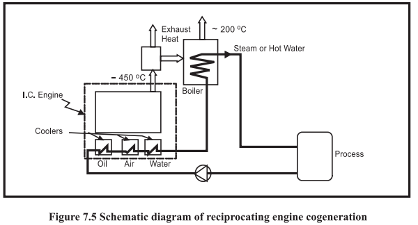
Reciprocating engine cogeneration systems
Also known as internal combustion (I. C.) engines, these cogeneration systems have high power
generation efficiencies in comparison with other prime movers. There are two sources of heat for
recovery: exhaust gas at high temperature and engine jacket cooling water system at low temperature
(see Figure 7.5). As heat recovery can be quite efficient for smaller systems, these systems are more
popular with smaller energy consuming facilities, particularly those having a greater need for electricity
than thermal energy and where the quality of heat required is not high, e.g. low pressure steam or hot
water.

Though diesel has been the most common fuel in the past, the prime movers can also operate with
heavy fuel oil or natural gas. These machines are ideal for intermittent operation and their performance
is not as sensitive to the changes in ambient temperatures as the gas turbines. Though the initial
investment on these machines is low, their operating and maintenance costs are high due to high wear
and tear.
Classification of Cogeneration Systems
Cogeneration systems are normally classified according to the sequence of energy use and the operating
schemes adopted.
A cogeneration system can be classified as either a topping or a bottoming cycle on the basis of the
sequence of energy use. In a topping cycle, the fuel supplied is used to first produce power and then
thermal energy, which is the by-product of the cycle and is used to satisfy process heat or other
thermal requirements. Topping cycle cogeneration is widely used and is the most popular method of
cogeneration.
Topping Cycle
The four types of topping cycle cogeneration systems are briefly explained in Table 7.1.

Bottoming Cycle In a bottoming cycle, the primary fuel produces high temperature thermal energy and the heat rejected
from the process is used to generate power through a recovery boiler and a turbine generator. Bottoming
cycles are suitable for manufacturing processes that require heat at high temperature in furnaces and
kilns, and reject heat at significantly high temperatures. Typical areas of application include cement,
steel, ceramic, gas and petrochemical industries. Bottoming cycle plants are much less common than
topping cycle plants. The Figure 7.6 illustrates the bottoming cycle where fuel is burnt in a furnace to
produce synthetic rutile. The waste gases coming out of the furnace is utilized in a boiler to generate
steam, which drives the turbine to produce electricity.
Factors Influencing Cogeneration Choice
The selection and operating scheme of a cogeneration system is very much site-specific and depends
on several factors, as described below:
Base electrical load matching In this configuration, the cogeneration plant is sized to meet the minimum electricity demand of the
site based on the historical demand curve. The rest of the needed power is purchased from the utility
grid. The thermal energy requirement of the site could be met by the cogeneration system alone or by
additional boilers. If the thermal energy generated with the base electrical load exceeds the plant’s
demand and if the situation permits, excess thermal energy can be exported to neighbouring customers.
Base thermal load matching
Here, the cogeneration system is sized to supply the minimum thermal energy requirement of the site.
Stand-by boilers or burners are operated during periods when the demand for heat is higher. The prime
mover installed operates at full load at all times. If the electricity demand of the site exceeds that which
can be provided by the prime mover, then the remaining amount can be purchased from the grid.
Likewise, if local laws permit, the excess electricity can be sold to the power utility.
Electrical load matching
In this operating scheme, the facility is totally independent of the power utility grid. All the power
requirements of the site, including the reserves needed during scheduled and unscheduled maintenance,
are to be taken into account while sizing the system. This is also referred to as a “stand-alone” system.
If the thermal energy demand of the site is higher than that generated by the cogeneration system,
auxiliary boilers are used. On the other hand, when the thermal energy demand is low, some thermal
energy is wasted. If there is a possibility, excess thermal energy can be exported to neighbouring
facilities.
Thermal load matching
The cogeneration system is designed to meet the thermal energy requirement of the site at any time.
The prime movers are operated following the thermal demand. During the period when the electricity
demand exceeds the generation capacity, the deficit can be compensated by power purchased from the
grid. Similarly, if the local legislation permits, electricity produced in excess at any time may be sold
to the utility.
Important Technical Parameters for Cogeneration
While selecting cogeneration systems, one should consider some important technical parameters that
assist in defining the type and operating scheme of different alternative cogeneration systems to be
selected.
Heat-to-power ratio and Energy Utilisation factor
Heat-to-power ratio is one of the most important technical parameters influencing the selection of the
type of cogeneration system. The heat-to-power ratio of a facility should match with the characteristics
of the cogeneration system to be installed.
It is defined as the ratio of thermal energy to electricity required by the energy consuming facility.
Though it can be expressed in different units such as Btu/kWh, kcal/kWh, lb./hr/kW, etc., here it is
presented on the basis of the same energy unit (kW).
Basic heat-to-power ratios of the different cogeneration systems are shown in Table 7.2 along with
some technical parameters. The steam turbine cogeneration system can offer a large range of heat-to-power ratios.
Cogeneration uses a single process to generate both electricity and usable heat or cooling. The
proportions of heat and power needed (heat: power ratio) vary from site to site, so the type of plant
must be selected carefully and appropriate operating schemes must be established to match
demands as closely as possible. The plant may therefore be set up to supply part or all of the site
heat and electricity loads, or an excess of either may be exported if a suitable customer is
available. The following Table 7.3 shows typical heat:power ratios for certain energy intensive
industries.
Cogeneration is likely to be most attractive under the following circumstances:
(a) The demand for both steam and power is balanced i.e. consistent with the range of
steam: power output ratios that can be obtained from a suitable cogeneration plant.
(b) A single plant or group of plants has sufficient demand for steam and power to permit
economies of scale to be achieved.
(c) Peaks and troughs in demand can be managed or, in the case of electricity, adequate
backup supplies can be obtained from the utility company.
The ratio of heat to power required by a site may vary during different times of the day and seasons
of the year. Importing power from the grid can make up a shortfall in electrical output from the
cogeneration unit and firing standby boilers can satisfy additional heat demand. Many large cogeneration
units utilize supplementary or boost firing of the exhaust gases in order to modify the heat: power ratio
of the system to match site loads.
Energy Utilisation Factor
EUF is the percentage of useful output (i.e.) a combination of electrical
output and thermal output to fuel heat input. The formula for EUF is given below.
The electrical output is the useful power generation from the turbine and the thermal output is the
useful extraction from turbine for process heating. The fuel heat input is the fuel flow rate multiplied
by its calorific value.
Quality of thermal energy needed The quality of thermal energy required (temperature and pressure) also determines the type of
cogeneration system. For a sugar mill needing thermal energy at about 120°C, a topping cycle
cogeneration system can meet the heat demand. On the other hand, for a cement plant requiring thermal
energy at about 1450°C, a bottoming cycle cogeneration system can meet both high quality thermal
energy and electricity demands of the plant.
Load patterns
The heat and power demand patterns of the user affect the selection (type and size) of the cogeneration
system. For instance, the load patterns of two energy consuming facilities shown in Figure 7.7 would
lead to two different sizes, possibly types also, of cogeneration systems.
Fuels available
Depending on the availability of fuels, some potential cogeneration systems may have to be rejected.
The availability of cheap fuels or waste products that can be used as fuels at a site is one of the major
factors in the technical consideration because it determines the competitiveness of the cogeneration
system.
A rice mill needs mechanical power for milling and heat for paddy drying. If a cogeneration system
were considered, the steam turbine system would be the first priority because it can use the rice husk
as the fuel, which is available as waste product from the mill.
System reliability
Some energy consuming facilities require very reliable power and/or heat; for instance, a pulp and
paper industry cannot operate with a prolonged unavailability of process steam. In such instances, the
cogeneration system to be installed must be modular, 1.e. it should consist of more than one unit so
that shut down of a specific unit cannot seriously affect the energy supply.
Grid dependent system versus independent system
A grid-dependent system has access to the grid to buy or sell electricity. The grid-independent system
is also known as a “stand-alone” system that meets all the energy demands of the site. It is obvious
that for the same energy consuming facility, the technical configuration of the cogeneration system
designed as a grid dependent system would be different from that of a stand-alone system.
Retrofit versus new installation
If the cogeneration system is installed as a retrofit, the system must be designed so that the existing
energy conversion systems, such as boilers, can still be used. In such a circumstance, the options for
cogeneration system would depend on whether the system is a retrofit or a new installation.
Electricity buy-back
The technical consideration of cogeneration system must take into account whether the local regulations
permit electric utilities to buy electricity from the cogenerators or not. The size and type of cogeneration
system could be significantly different if one were to allow the export of electricity to the grid.
Local environmental regulation
The local environmental regulations can limit the choice of fuels to be used for the proposed cogeneration
systems. If the local environmental regulations are stringent, some available fuels cannot be considered
because of the high treatment cost of the polluted exhaust gas and in some cases, the fuel itself.
Prime Movers for Cogeneration
Steam Turbine
Steam turbines (Figure 7.8) are the most commonly employed prime movers for cogeneration
applications in the steam turbine; the incoming high pressure steam is expanded to a lower pressure
level, converting the thermal energy of high pressure steam to kinetic energy through nozzles and then
to mechanical power through rotating blades.
Back Pressure turbine: In this type steam enters the turbine chamber at High Pressure and expands
to Low or Medium Pressure. Enthalpy difference is used for generating power / work. Depending on the pressure (or temperature) levels at which process steam is required, backpressure
steam turbines can have different configurations as shown in Figure 7.9.
In extraction and double extraction backpressure turbines, some amount of steam is extracted from
the turbine after being expanded to a certain pressure level. The extracted steam meets the heat
demands at pressure levels higher than the exhaust pressure of the steam turbine.
The efficiency of a backpressure steam turbine cogeneration system is the highest. In cases where
100 per cent backpressure exhaust steam is used, the only inefficiencies are gear drive and electric
generator losses, and the inefficiency of steam generation. Therefore, with an efficient boiler, the
overall thermal efficiency of the system could reach as much as 90 per cent.
Extraction Condensing turbine:
In this type, steam entering at High / Medium Pressure is extracted
at an intermediate pressure in the turbine for process use while the remaining steam continues to
expand and condenses in a surface condenser and
work is done till it reaches the Condensing
pressure.(vacuum).
In Extraction cum Condensing steam turbine as
shown in Figure 7.10, high Pressure steam enters
the turbine and passes out from the turbine
chamber in stages. In a two stage extraction cum condensing turbine MP steam and LP steam pass out to meet the process needs. Balance quantity condenses in the surface condenser. The Energy difference is used for generating Power. This configuration meets the heat-power requirement of the process.
The extraction condensing turbines have higher power to heat ratio in comparison with backpressure
turbines. Although condensing systems need more auxiliary equipment such as the condenser and
cooling towers, better matching of electrical power and heat demand can be obtained where electricity
demand is much higher than the steam demand and the load patterns are highly fluctuating.
The overall thermal efficiency of an extraction condensing turbine cogeneration system is lower than
that of back pressure turbine system, basically because the exhaust heat cannot be utilized (it is normally
lost in the cooling water circuit). However, extraction condensing cogeneration systems have higher
electricity generation efficiencies.
Gas Turbine
The fuel is burnt in a pressurized combustion chamber using combustion air supplied by a compressor that is integral with the gas turbine. In conventional Gas turbine (Figure 7.11), gases enter the turbine at a temperature range of 900 to 1000 °C and leave at 400 to 500 °C. The very hot pressurized gases are used to turn a series of turbine blades, and the shaft on which they are mounted, to produce mechanical energy. Residual energy in the form of a high flow of hot exhaust gases can be used to meet, wholly or partly, the thermal (steam) demand of the site. Waste gases are exhausted from the turbine at 450 °C to 550 °C, making the gas
turbine particularly suitable for high-grade heat supply.
The available mechanical energy can be applied in the following ways:
1.To produce electricity with a generator (most applications);
2.To drive pumps, compressors, blowers, etc.
A gas turbine operates under exacting conditions of high speed and high temperature. The hot gases
supplied to it must therefore be clean (i.e. free of particulates which would erode the blades) and must
contain not more than minimal amounts of contaminants, which would cause corrosion under operating
conditions. High-premium fuels are therefore most often used, particularly natural gas. Distillate oils
such as gas oil are also suitable, and sets capable of using both are often installed to take advantage
of cheaper interruptible gas tariffs. LLPGs and Naphtha are also suitable, LPG being a possible fuel
in either gaseous or liquid form.
Gas Turbine Efficiency
Turbine Efficiency is the ratio of actual work output of the turbine to the net input energy supplied in
the form of fuel. For stand-alone Gas Turbines, without any heat recovery system the efficiency will
be as low as 35 to 40%. This is attributed to the blade efficiency of the rotor, leakage through clearance
spaces, friction, irreversible turbulence etc.
Since Exhaust gas from the Gas Turbine is high, it is possible to recover energy from the hot gas by a
Heat Recovery Steam Generator and use the steam for process.
Net Turbine Efficiency
Above efficiency figures did not include the energy consumed by air compressors, fuel pump and other
auxiliaries. Air compressor alone consumes about 50 to 60 % of energy generated by the turbine. Hence
net turbine efficiency, which is the actual energy output available will be less than what has been
calculated. In most Gas Turbine plants, air compressor is
an integral part of Turbine plant.
Reciprocating Engine Systems
This system (Figure 7.12) provides process heat or steam
from engine exhaust. The waste heat from engine jacket
and lube oil cooler may also be used to provide hot water or hot air. There are, however, limited applications for
this.
As these engines can use only fuels like HSD, distillate, residual oils, natural gas, LPG etc. and as they are not economically better than steam/gas turbine, their use is not widespread for co-generation. One more reason for this is the engine maintenance requirement.
Typical Cogeneration Performance Parameters
The following Table 7.4 gives typical Cogeneration Performance Parameters for different Cogeneration
Packages giving heat rate, overall efficiencies etc.
Relative Merits of Cogeneration Systems The following Table 7.5 gives the advantages and disadvantages of various co-generation systems:
Steam Turbine Efficiency
Turbine efficiency
Several terms are in use with respect to turbine efficiency.
1.“Turbine cylinder efficiency is given as ratio of actual enthalpy drop and isentropic enthalpy
drop, as a percentage.
2.”
Performance of steam turbine is also assessed by a pressure survey to establish extent of
performance deviation.
3.Performance of steam turbine is also expressed as heat rate, which is the quantity of heat in kcal
or KJ required to generate 1 kWh of electrical power output.”
4.“Turbine efficiency is the ratio useful heat and power output, to the heat input to the turbine in
Keal or KJ, expressed as a percentage.
5.”
Performance of steam turbines is also expressed in terms of Theoretical Steam Rate (TSR)
and Actual Steam Rate (ASR), to generate one kWh of electric power. TSR and ASR can be
determined from the power generation and the steam input data.
Methods of Turbine performance monitoring
Cylinder efficiency
The ratio of the actual heat drop in a cylinder to the isentropic heat drop is cylinder efficiency. As
illustrated in Figure 7.13, the parameters at Turbine inlet and exhaust are measured, to arrive at effective
heat drop A.
If there were no friction, turbulence, windage and other losess, the expansion would be isentropic and
heat drop would be B. The cylinder efficiency is thus expressed as A/B in percentage.
Turbine Pressure survey:
A very useful assessment of internal condition of a turbine is achieved by carrying out a pressure
survey. Pressure is noted at various tapping points across turbine expansion path and this pressure
profile is validated against the same at design conditions, to infer internal condition of turbine. It is
important that pressure gauges used are accurate and that all readings are obtained while load is steady.
Pressure survey should be carried out on each running machine frequently.
Turbine Heat rate:
Heat rate is the heat input to turbine, needed to produce 1 kWh of electricity. Turbine heat rate is
expressed in kJ/kWh. The inverse relation between heat rate and efficiency is applicable only to a
power plant, since all the input energy is deployed for power generation alone.
Notes on cogeneration efficiency
1.Cogeneration efficiency, (being useful heat output by heat input) is not necessarily inverse of heat
rate, as in case of a typical thermal plant, since the useful heat output to process is not accounted
in heat rate calculation.
2.Back pressure steam turbines offer better system efficiency up to 85% since all the exhaust heat
in steam is used in process, as useful heat.
3.Extraction cum back pressure and extraction cum condensing turbines are deployed where
flexibility for meeting various steam and power demands is called for. As the steam quantity
passed through condenser increases, the heat rate becomes higher, since loss of latent heat in
condenser is significant. The extraction condensing cogeneration systems, on this account, need
more heat input (1.e. higher heat rate) and therefore are less efficient then back pressure type.
4.Fully condensing turbines are used only by utility plants, and they have a huge share of heat input
lost through condenser & cooling tower system.
5.In Industrial Cogeneration systems, back up pressure or extraction back pressure turbines are
preferred for economy, efficiency and flexibility.
Cogeneration Heat Rate and Efficiency Assessment -Illustrative Case
Co-generation Plant Features
Boiler
Coal Fired FBC Water Tube Type, 35 TPH, 66 ata, 505 + 5 °C and 1537 m? Heating Surface Area,
83% Boiler efficiency
Boiler feed water temperature = 60 °C. Feed water enthalpy = 251 kJ/kg
Turbine
Bleed Cum Extraction Cum Condensing, 6000 kW Alternator, 63 kg / cm? (g) Steam inlet pressure at
500 °C and 34800 kg/hr Flow, Extraction Pressure of 8 kg/cm’, Extraction Flow of 13470 kg/hr, Bleed
extraction Pressure of 1.23 kg/cm? and Flow of 3550 kg/hr for deaerator, Exhaust Pressure of 0.10 ata,
Turbine rpm 8280 and Alternator rpm 1500.
Surface Condenser
Fixed Tube, Two Pass (Divided Type) Condenser, Steam Load 22000 kg/hr @ 0.095 ata and 40°C,
CW Flow 1514 m?/hr, HT Area 649.2 m/2.
The performance of cogeneration plant at various settings is as follows:


Trigeneration
Cogeneration
Trigeneration refers to simultaneous generation of steam (heat), power and refrigeration through
integrated systems. Industries requiring electricity, steam and cooling such as food processing and
cold storages find the concepts of tri-generation very attractive.
A combined cycle trigeneration plant could typically consist of a gas turbine generator, waste heat
recovery boiler, steam turbine, generator, and absorption chiller, to meet 100% of the facility energy
needs. Whenever the power is surplus, it is sold to the grid.
An illustrative trigeneration system schematic is presented in Figure 7.14.
Microturbine
Cogeneration
The Micro steam Turbine Power System is a compact, efficient power system that generates electricity
from pressure energy previously wasted in the steam pressure reducing valves.
In a typical steam system, a Pressure Reducing Valve (PRV) reduces the steam pressure from P1 to
P2 (Figure 7.15a). This pressure reduction happens in such a manner that the total energy content
(enthalpy) does not change (H1 = H2) and no shaft work is done.
On the other hand, when steam goes through a steam turbine, it expands and the steam pressure reduces
from P1 to P2 (Figure 7.15b). The steam turbine produces shaft horsepower and as a result, the steam
exit energy content (enthalpy) is lower when compared to the PRV case.
Steam is used for heating purposes in the plant. The process heat duty is fixed by the plant demand.
Since the steam supplied to the process has a lower enthalpy, an additional amount of steam is required
to ensure the same available heat duty. This additional amount of steam has an associated cost. Hence,
power generated from a backpressure steam turbine is not free.
Nevertheless, using a backpressure steam turbine can improve the overall plant and global energy
efficiency and more importantly, it can reduce total operating costs.
Example: Pressure reducing valve versus back pressure turbine
A chemical plant generates steam at 17.6 kg/cm? (g) which is further reduced to 1.8 kg/cm? (g) through
a pressure reducing valve, for utilization in the process. The process requires 5189 MCal/hr of heat.
The plant has planned to replace the PRV with a back pressure steam turbine.
Calculate the net savings per annum if the plant operates 8000 hrs/annum with the following data and
the data provided in the schematic diagrams.
Calorific value of fuel - 10,000 kcal/kg,
Fuel cost - Rs. 25,000/Tonne,
Grid cost of electricity charge - Rs. 6/kWh.
Gear box efficiency - 98%
Alternator efficiency - 98%
Mechanical efficiency of turbine - 97%
a) Boiler and PRV operation

b) Boiler and Micro turbine operation
Solved Example:
The schematic of a back pressure steam turbine cogeneration system of process plant operating round
the clock with operating data is depicted below.
If the steam requirement of the process is to be increased to 44TPH which can be met by the existing
boiler through the back pressure turbine,
a) Find out the reduction in cost of electrical energy drawn from the grid per day due to additional
power generation ,assuming the same steam to power recovery as in the existing case and at a
grid electricity cost of Rs.7/kWh, Aux power remains the same.
b) Also find out the additional coal requirement per day?
------------------------
Chapter 8


Comments
Post a Comment