ENERGY_PERFORMANCE_ASSESSMENT_FOR_EQUIPMENT_AND_UTILITY_SYSTEMS_(Chapter 3:Energy Performance Assessment of Cogeneration Systems With Steam & Gas turbine)


ENERGY_PERFORMANCE_ASSESSMENT_FOR_EQUIPMENT_AND UTILITY SYSTEMS

(Chapter 3:Energy Performance Assessment of Cogeneration Systems With Steam & Gas turbine)

Introduction

Cogeneration systems can be broadly classified as those using steam turbines, Gas turbines and DG sets. Steam turbine cogeneration systems involve different types of configurations with respect to mode of  power generation such as extraction, back pressure or a combination of backpressure, extraction and condensing.

Gas turbine with heat recovery steam generators is another mode of cogeneration. Depending on power and steam load variations in the plant the entire system is dynamic. A performance assessment would yield valuable insights into cogeneration system performance and need for further optimization.

Purpose of the Performance Test

The purpose of the cogeneration plant performance test is to determine the power output and plant heat rate. In certain cases, the efficiency of individual components like steam turbine is addressed specifically where performance deterioration is suspected. In general, the plant performance will be compared with the base line values arrived at for the plant operating condition rather than the design values. The other purpose of the performance test is to show the maintenance accomplishment after a major overhaul. In some cases the purpose of evaluation could even be for a total plant revamp.

Performance Terms and Definitions

Overall Plant Performance

Steam Turbine Performance
Gas Turbine and Heat Recovery Steam Generator Performance

Reference Standards

ASME performance test codes

Field Testing Procedure

The test procedure for each cogeneration plant will be developed individually taking into consideration the plant configuration, instrumentation and plant operating conditions.

Test Duration

The test duration is site specific and in a continuous process industry, 8-hour test data should give reasonably reliable data. In case of an industry with fluctuating electrical/steam load profile, a set of 24-hour data sampling to be taken for a representative period.

Measurements and Data Collection

The suggested instrumentation (online/ field instruments) for the performance measurement is as under:

Steam flow measurement : Orifice flow meters 

Fuel flow measurements : Volumetric measurements / Mass flow meters

Air flow / Flue gas flow : Venturi / Orifice flow meter / Ion gun / Pitot tubes

Flue gas analysis : Zirconium Probe Oxygen analyser

Unburnt analysis : Gravimetric analysis

Temperature : Thermocouple

Cooling water flow : Orifice flow meter / weir /channel flow/

non-contact flow meters

Pressure : Bourdon Pressure Gauges

Power : Trivector meter / Energy meter

Condensate : Orifice flow meter

It is essential to ensure that the data is collected during steady state plant running conditions. Among others the following are essential details to be collected for cogeneration plant performance evaluation.

I. Thermal Energy:


II. Electrical Energy:

1. Total power generation for the trial period from individual turbines.

2. Hourly average power generation

3. Quantity of power import from utility ( Grid )

4. Auxiliaries power consumption

Calculations for Steam Turbine Cogeneration System

The process flow diagram for cogeneration plant is shown in Figure 3.1. The following calculation procedures have been provided in this section.

1.Turbine cylinder efficiency

2.Overall plant heat rate

Step 1:
Calculate the actual heat extraction in turbine at each stage,
Steam Enthalpy at turbine inlet : H1 kcal/kg
Steam Enthalpy at 1“ extraction : H2 kcal/kg
Steam Enthalpy at Condenser : H3* kcal / kg
* Due to wetness of steam in the condensing stage, the enthalpy of steam cannot be considered as equivalent to saturated steam. Typical dryness value is 0.88 — 0.92. This dryness value can be used as first approximation to estimate heat drop in the last stage. However it is suggested to calculate the last stage efficiency from the overall turbine efficiency and other stage efficiencies.

Heat extraction from inlet :                                    H1- H2 kCal/kg
to extraction
Heat extraction from :                                            H2— H3 kCal / kg
Extraction to condenser

Step 2:
From Mollier diagram (H-f Diagram) estimate the theoretical heat extraction for the conditions
mentioned in Step 1. Towards this:
a) Plot the turbine inlet condition point (H,) in the Mollier chart — corresponding to steam
pressure (P,) and temperature.
b) Since expansion in turbine is an adiabatic process, the entropy is constant. Hence draw a
vertical line from inlet point (parallel to y-axis) upto the extraction pressure (P,). Read the
corresponding enthalpy H, ,..
c) Plot the extraction condition point (H,) in the Mollier chart — corresponding to steam
pressure (P,) and temperature.
d) Draw a vertical line from extraction point (parallel to y-axis) upto the condensing pressure
(P,). Read the corresponding enthalpy H3-i8
e) Compute the theoretical heat drop for different stages of expansion.

Step 3:

Compute turbine stage (isentropic) efficiency

Step 4:
To calculate the turbine power output (Pt)
Step 5:
To calculate the generator power output (Pg)
Examples
Example 3.6.1
From the data given for an extraction condensing turbine, calculate the stage-wise (isentropic) turbine
efficiency and power output.


Example 3.6.2
Calculate the following performance parameters of the gas turbine, details of which are given below
1. Overall plant fuel rate
2. Overall plant heat rate
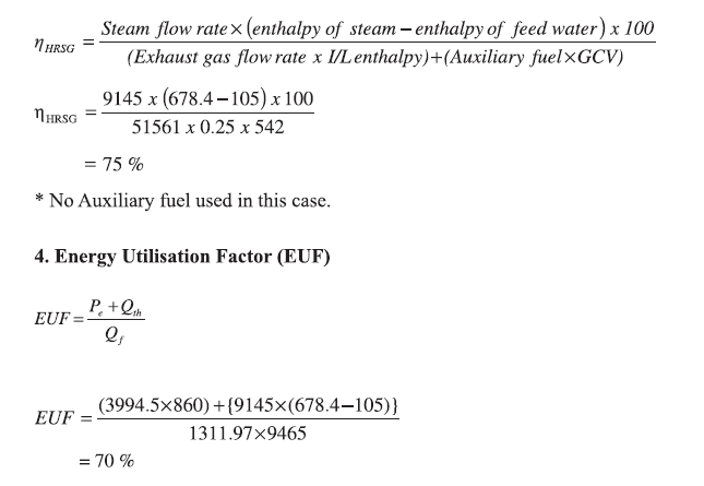
3. Thermal efficiency of HRSG
4. Energy Utilisation Factor (EUF)
1. Determination of overall plant fuel rate
Fuel consumption = 1312 Sm3/hr
Electrical power output = 3994.5 kW
Overall plant fuel rate = 1312/3994.5
= 0.32844 Sm?/kWh

2. Overall plant heat rate
Overall plant heat rate, kCal/kWh
=Overall plant fuel rate, Sm3 /kWhxGCV of fuel, kCa/ lSm ?
= 0.32844 x9465
= 3109 kCal/kWh

3. Thermal efficiency calculations for HRSG

Case Study of Bottoming Cycle Cogeneration in a Cement Industry
Waste heat sources in a cement plant
In cement manufacturing process, raw materials are burnt in the Rotary Kiln and the fuel used for combustion generates huge quantity of exhaust gases. A part of the heat in the flue gas is utilized for pre heating the raw materials going to kiln in preheaters. Along with this the heat in flue gas is also used remove the moisture of coal (used as fuel) and limestone (main raw material for cement production) during grinding. Further the heat may also be used to dry Puzzolonic materials such as fly ash or slag used in the manufacture of blended cement.
Based on the number of preheater stages, kiln gases exit at around 300 — 400°C in case of 4 stage preheater and 200 — 300°C in case of 5 — 6 stage pre-heater. The quantity of heat from pre-heater exit gases ranges from 180-250 kcal/kg clinker.
The solid material i.e. clinker coming out of the rotary kiln is at around 1000 °C and is cooled to 100- 120 °C temperature using ambient air in clinker cooler. This generates hot air of about 200-300 °C having heat of 80-130 kcal/kg clinker. Part of the hot air generated is used as combustion air in kiln furnaces & remaining is exhausted to atmosphere.
Waste gas discharged from Kiln Preheater and clinker cooler thus contains useful energy that can be converted into power by installation of waste heat boiler that runs a steam turbine. The generation potential depends on the Kiln capacity, number of pre-heater stages, heat required to remove moisture in raw material and coal.

Waste heat recovery based power generation
The waste heat recovery (WHR) system, effectively utilises the available waste heat from exit gases of pre-heater and clinker cooler. The WHR system consists of Suspension pre-heater (SP) boiler, Air Quenching Chamber (AQC) boiler, steam turbine generator, distributed control system (DCS), water-circulation, system and dust-removal system etc as shown in Figure 3.3
Process requirements decide the output temperature of flue gas from the waste heat recovery boilers thus deciding available heat to be recovered. Seasonal variations in the demand of flue gas for drying raw material also to be met while designing the system.

Calculation of power generation potential

1. Kiln capacity: 4300 Tons per Day (179.167 Tons Per Hour)

2. No of stages in the preheater: 5

3. Preheater exit gas details:

Volume (mph): 167559 Nm3/hr

Specific heat capacity (Cph) : 0.355 kcal/kg/ Deg C

Inlet Temperature T: 295 Deg C

Outlet temperature with WHRB: 195 Deg C

4. Cooler exit gas details:

Volume (mc) : 91000 Nm3/hr

Specific heat capacity (Cc) : 0.316 kcal/kg/ Deg C

Inlet Temperature T: 360 Deg C

Outlet temperature with WHRB: 130 Deg C

5. Overall Conversion efficiency —Pre heater section: 20%

6. Overall Conversion efficiency- Cooler section: 21 %

Calculations:


Solved Example:

A common plant facility is installed to provide steam and power to textile and paper plant with a cogeneration system. The details and operating parameters are given below:


Other data:

- Turbine, alternator and other losses = 8%

- Specific steam consumption in paper industry= 5 Tons/Ton of paper

- Specific power consumption in paper industry= 600 kWh/Ton of paper

Calculate:

i. Coal consumption in boiler per hour or per day.

il. Power generation from co-generation plant

iil. If 10% is auxiliary power consumption in co-generation plant, how much power is consumed

by the textile industry per hour?

iv. What is the gross heat rate of turbine?


ii) Gross power generation from co-generation plant

Total enthalpy input to turbine = 60,000 x 810 = 48.6 Million kcal.

Total enthalpy out put through back pressure = 60,000* 660 = 39.6 Million kcal

Enthalpy difference = 48.6- 39.6 =9 Million kcal/hr

Turbine, alternator and other losses (8%) = 9x0.08 = 0.72 Million kcal/hr

Useful energy for power generation = 9 - 0.72 = 8.28 Million kcal/hr

Power generation from co-generation plant = 8.28 x 10°/860 = 9628 kWh

il) If 10% is auxiliary power consumption in co-generation plant, power consumed by textile

industry

10% of total power generation = 9628 x 0.10 = 962.8 kWh

Total power consumed by industries = 9628 — 962.8 = 8665.2 kWh

Total steam consumption in paper plant 40 tons/hr. and specific steam consumption 5 ton/ton

of paper. So Paper production per hour is 8 tons.

Specific power consumption = 600kWh/ton.

Total power consumption in paper industry = 8 x 600 = 4800kWh

Total power consumption in textile industry = 8665.2- 4800 = 3865.2 kWh

iv) Gross heat rate =Input enthalpy — Output enthalpy/ Gross generation

= (48.6- 39.6) 10°/ 9628 

= 934.7 keal/kWh

-----------------------

Chapter 2

Chapter 4

Comments

Followers

Popular posts from this blog

Welder qualification procedure as per ASME Sec IX

  WELDER QUALIFICATON PROCEDURE (FOR PLATE &PIPING) 1.      Test positions for performance qualification 1.1   Positions (Groove weld) plate & pipe: - An angular deviation of plus or minus 15° From specified horizontal and vertical planes is permitted during welding. Position for qualification as per ASME IX QW-461.3 & QW-461.4 Table. 1 Plate Positions Pipe Positions a)        Vertical Position 3G (Fig.1a) b)        Overhead Positions 6G- (Fig.1b)   b) Overhead Position 4G (Fig.1a)               Fig. 1 Position of test peace for Groove weld (Plate & Pipe). 1.2   Test Positions for Fillet Welds: - An angular deviation of plus or minus 15° from the specified horizontal and vertical planes is permitted during welding. Position for qualification as per ASME QW-461.5 Table.2 Fillet joint Positions         a)   Vertical 3F        b)

Lathe machine

                                                       TYPES OF LATHE  Lathes are manufactured in a variety of types and sizes, from very small bench lathes used for precision work to huge lathes used for turning large steel shafts. But the principle of operation and function of all types of lathes is same. The different types of lathes are: 1. Speed lathe ( a ) Wood working ( b ) Spinning ( c ) Centering ( d ) Po1ishing   2. Centre or engine lathe ( a ) Be1t drive ( b ) Individual motor drive ( c ) Gear head lathe   3. Bench lathe   4. Tool room Lathe   5. Capstan and Turret 1athe   6. Special purpose lathe ( a ) Whee1 lathe ( b ) Gap bed lathe ( c ) Dup1icating lathe ( d ) T-lathe   7.Automatic lathe Speed Lathe Speed lathe is simplest of all types of lathes in construction and operation. The important parts of speed lathe are following- (1) Bed (2) Headstock (3) Tailstock, and (4) Tool post mounted on an adjustable slide.   It has no

Minimum required thickness of process pipeline (Engineering calculation)

Pressure Calculation Calculator:Minimum required thickness of pipeline for service as per ASME B31.3 Design Pressure (PSI): Diameter (inch): Stress 'S' (PSI): Quality Factor 'E': Weld Joint Reduction Factor 'W': Coefficient 'Y': Calculate Results: Min. Reqired Thickness tm (inch): 12.5% Allowance (inch): Mini. Required Thicknes (mm): After getting 12.5% allowance (inch) value again check ASME B36.10 or API 574 piping thickness table and choose thicknes value higher then this value for service. Calculating the Minimum Required Thickness of Pipelines for Service as per ASME B31.3 Introduction: In the field of engineering, designing safe and reliable pipelines is of utmost importance. The American Society of Mechanical Engineers (ASME) B31.3 code provides guidelines for the design and construction of process piping systems. One cr

Ultrasonic Flaw Detection: Unveiling the Power of Sound in Non-Destructive Testing

Introduction: Non-destructive testing (NDT) techniques play a vital role in ensuring the integrity and safety of structures, materials, and components in various industries. Among the array of NDT methods available, ultrasonic flaw detection stands out as a powerful and versatile technique. In this blog, we will explore the fundamentals of ultrasonic flaw detection, its applications, and the benefits it offers in detecting and characterizing defects without causing damage. Join us as we dive into the world of sound waves and their ability to reveal hidden flaws. 1. Understanding Ultrasonic Flaw Detection: 1.1 The Basics of Ultrasonics: We'll introduce the principles of ultrasonics, explaining how sound waves are generated, propagated, and detected. 1.2 Interaction with Materials: We'll explore how ultrasonic waves interact with different materials, including their reflection, transmission, and absorption behaviors. 2. How Ultrasonic Flaw Detection Works: 2.1 Transducers: We'

Calculator: Remaining Thickness of Pressure vessel API 510 (Identify remaining thickness is safe/unsafe)

Thickness Calculation Remaining Thickness of Pressure vessel to identify safe for service Design Pressure (psi): Radius (inch): Stress (psi) ASME Sec VIII Div 1: Efficiency 'E': T(nominal) (inch): Metal Loss (inch): Calculate   Remaining Thickness of Pressure vessel API 510  (Identify remaining thickness is safe/unsafe) Introduction: In the field of pressure vessel inspection and maintenance, determining the remaining thickness of the vessel is of utmost importance. This calculation helps assess the structural integrity of the vessel and ensures its safe operation. In this blog post, we will explore the method for calculating the remaining thickness of a pressure vessel as per API 510 standards. Formula for Minimum Thickness (Tmin): The API 510 standard

Purging Gas in Gas Tungsten Arc Welding: Enhancing Weld Quality and Integrity

Introduction: In the realm of welding, achieving high-quality welds with excellent integrity is paramount. One crucial technique that aids in this endeavor is the use of purging gas. Purging gas plays a vital role in preventing oxidation and ensuring a clean, controlled environment during welding. In this blog, we will explore the significance of purging gas, its purpose, techniques, and benefits in various welding applications. Join us as we delve into the world of purging gas and its impact on weld quality. Back purging is most important phenomenon in GTAW process because this process is mostly used in Stainless steel. Stainless steel is widely used fabrication of chemical, petrochemical, food etc. plant. All thin section and root welding is performed by GTAW process. GTAW process is also very popular in Aluminum welding. In all large diameter pipe the root pass welding is done by GTAW process where the back purging is mandatory. Purging gas protect the weld metal fro

Energy efficiency in Thermal utilities (Chapter 3: Steam System)

  Energy efficiency in Thermal utilities  (Chapter 3: Steam System) Introduction  Steam has been a popular mode of conveying energy since the industrial revolution. Steam is used for generating power and also used in process industries such as sugar, paper, fertilizer, refineries, petrochemicals, chemical, food, synthetic fiber and textiles. The following characteristics of steam make it so popular and useful to the industry:  ¢ Highest specific heat and latent heat ¢ Highest heat transfer coefficient e Easy to control and distribute Cheap and inert   Properties of Steam  Water can exist in the form of solid, liquid and gas as ice, water and steam respectively. If heat energy is added to water, its temperature rises until a value is reached at which the water can no longer exist as a liquid. We call this the “saturation” point and with any further addition of energy, some of the water will boil off as steam. This evaporation requires relatively large amounts of energy, and whil